
Microphone and stereo audio monitor combination with four contact plug connector

a technology of microphone and stereo audio, which is applied in the field of audio monitors, can solve the problems of incompatibility problems, increased complexity of technology convergence, and inability to provide accessories that are compatible with more than a single manufacturer's devices

Inactive Publication Date: 2008-03-20
LOGITECH INT
View PDF5 Cites 3 Cited by
  • Summary
  • Abstract
  • Description
  • Claims
  • Application Information

AI Technical Summary

Problems solved by technology

In addition to the effects of having a wide variety of available music players, audio formats and media types, technology convergence has added another level of complexity to the audio industry.
As device complexity increases, it becomes increasingly difficult to provide accessories that are compatible with more than a single manufacturer's devices and, in some instances, compatible with more than a single device from a single manufacturer.
Some incompatibility issues arise due to differences in device form factor.
Other incompatibility issues are due to the lack of an industry standard.
Still other incompatibility issues occur when manufacturers attempt to retain market share by forcing the end users of their products to purchase accessories from them in order to insure compatibility with the previously purchased device.
Unfortunately if the audio monitors are combined with another accessory, for example a microphone, differences between device and monitor / microphone interfaces may require the user to purchase a different monitor / microphone combination for each device as well as whenever a device is replaced.
Thus, the lack of monitor / microphone combination interchangeability leads to undue user expense, user confusion, and unnecessary accessory duplication.

Method used


Image

  • Microphone and stereo audio monitor combination with four contact plug connector
  • Microphone and stereo audio monitor combination with four contact plug connector
  • Microphone and stereo audio monitor combination with four contact plug connector

Examples


Embodiment Construction

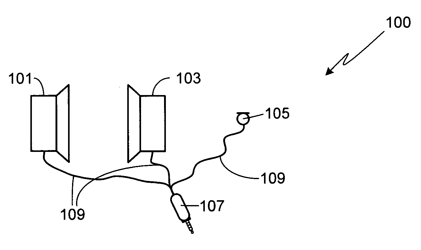
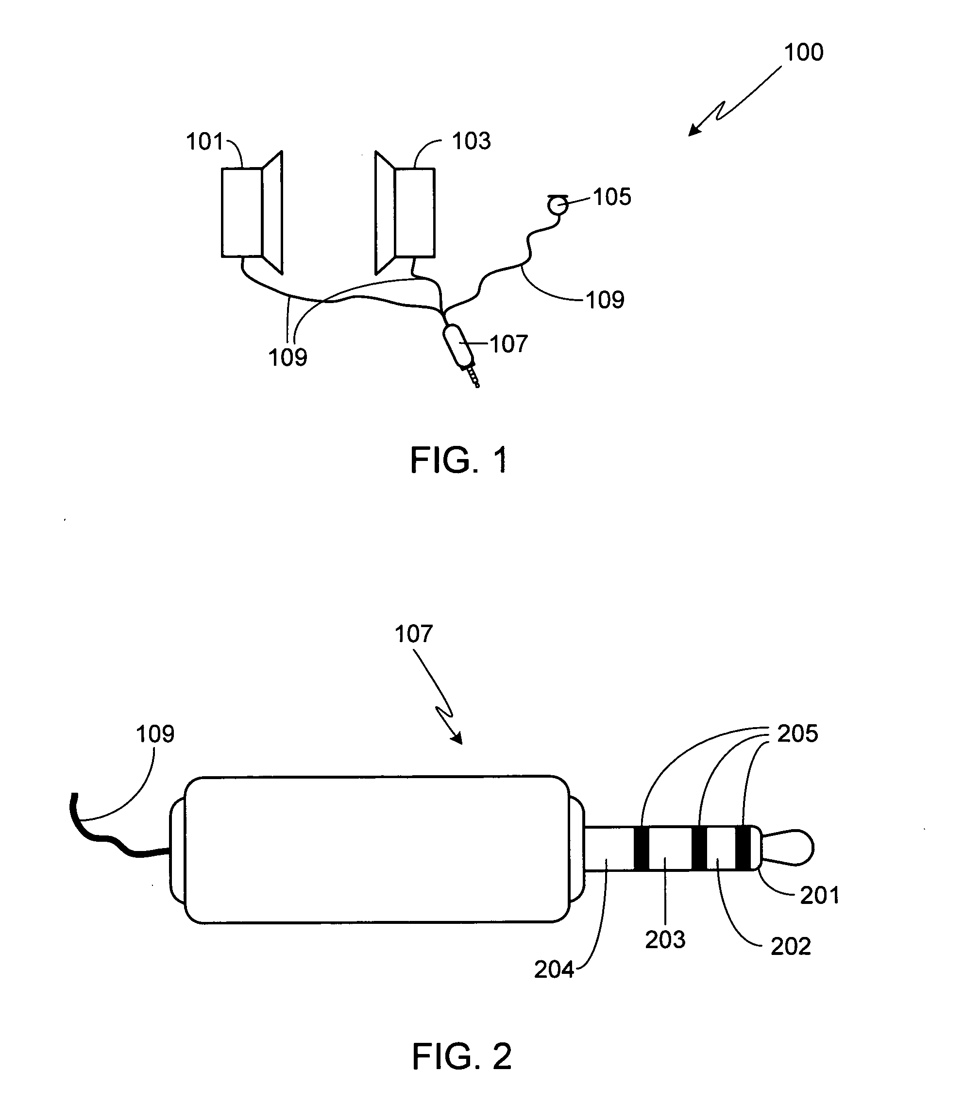
[0013]FIG. 1 is an illustration of an audio monitor / microphone combination 100 in accordance with the invention. The system includes a pair of audio monitors 101 and 103, also referred to herein as earphones, and a microphone 105. The audio monitors and the microphone are electrically connected to a plug connector 107 via cables 109.

[0014]FIG. 2 is a detailed illustration of plug connector 107. As shown, plug connector 107 includes four contact regions 201-204 separated by three electrically insulating rings 205. Plug connector 107 is configured such that tip contact region 201 corresponds to the left-hand speaker channel input, contact region 202 corresponds to the right-hand speaker channel input, contact region 203 corresponds to the microphone (+ve) output, and contact region 204 corresponds to both the speaker ground and the microphone ground. Although other sizes can be used, preferably plug connector 107 is a standard 3.5 millimeter (i.e., miniature) plug.

[0015]By using a sta...


PUM


Abstract

An audio monitor / microphone combination coupled to a four contact plug connector is provided. Exemplary audio monitors include ear buds, in ear monitors, over-the-head headsets, over-the-ear headsets, clip-on headsets, and behind-the-neck headsets. Exemplary microphones include boom-mounted microphones, earphone integrated microphones, microphones located on (or integrated within) the headset cable, and lanyard mounted microphones. The plug connector is configured such that the tip contact region corresponds to the left-hand speaker channel input, the second contact region adjacent to the tip contact region corresponds to the right-hand speaker channel input, the third contact region adjacent to the second contact region corresponds to the microphone output, and the fourth contact region adjacent to the third contact region corresponds to both the speaker ground and the microphone ground. Insulating rings are interposed between each pair of contact regions. Preferably an adaptor is included with the audio monitor / microphone combination as part of an accessory kit.

Description

FIELD OF THE INVENTION[0001]The present invention relates generally to audio monitors and, more particularly, to an audio device accessory that combines stereo audio monitors with a microphone.BACKGROUND OF THE INVENTION[0002]Currently the audio industry is undergoing dramatic changes. These changes are due in large part to the rapid proliferation of a wide variety of portable audio systems such as CD players, MP3 players, ATRAC3 players, WMA players, AM / FM radios, satellite receivers, DVD players, media centers and personal computers. These devices use various media (e.g., CDs, tape, flash memory, hard drives, etc.) to store content that may be obtained by live broadcast (AM / FM / satellite) or by connecting to any of a variety of content providers via the Internet, phone lines, etc.[0003]In addition to the effects of having a wide variety of available music players, audio formats and media types, technology convergence has added another level of complexity to the audio industry. It h...

Claims


Application Information

Patent Timeline
IPC IPC(8): H04B3/00
CPCH04R5/00
Inventor DYER, MEDFORD ALAN
Owner LOGITECH INT
Learn More