Ball thrower

Inactive Publication Date: 2008-03-27
CATTLIN BRETT
View PDF6 Cites 13 Cited by
  • Summary
  • Abstract
  • Description
  • Claims
  • Application Information

AI Technical Summary

Problems solved by technology

However, this can be a strenuous activity on the human arm which can also involve the dog walker having to pick up a muddy, me

Method used


Image

  • Ball thrower
  • Ball thrower
  • Ball thrower

Examples


Embodiment Construction

[0033]The present invention proposes a lightweight and small pocket sized ball throwing device that can easily be attached or incorporated into any standard / textile / leather or retractable dog lead or purpose made length of strap. The ball throwing device can be attached to a dog leash or length of strap using the purposely designed handle. The strap / dog lead attachment means is mounted on the outside of the cup opposite to the open mouth of the cup, preferably centrally. With the ball throwing device securely attached to a dog leash, the clasp end of the dog leash can then be connected to a supplied retaining ring located on the leash handle. The ball throwing device can be used for picking a ball up hands-free. This is achieved by placing the ball throwing device over a ball and pressing down firmly and is enabled in that the substantially semi-spherical ball housing is slightly over-sized so that the widest dimension of the housing (i.e. the diameter) is greater than the widest di...


PUM


Abstract

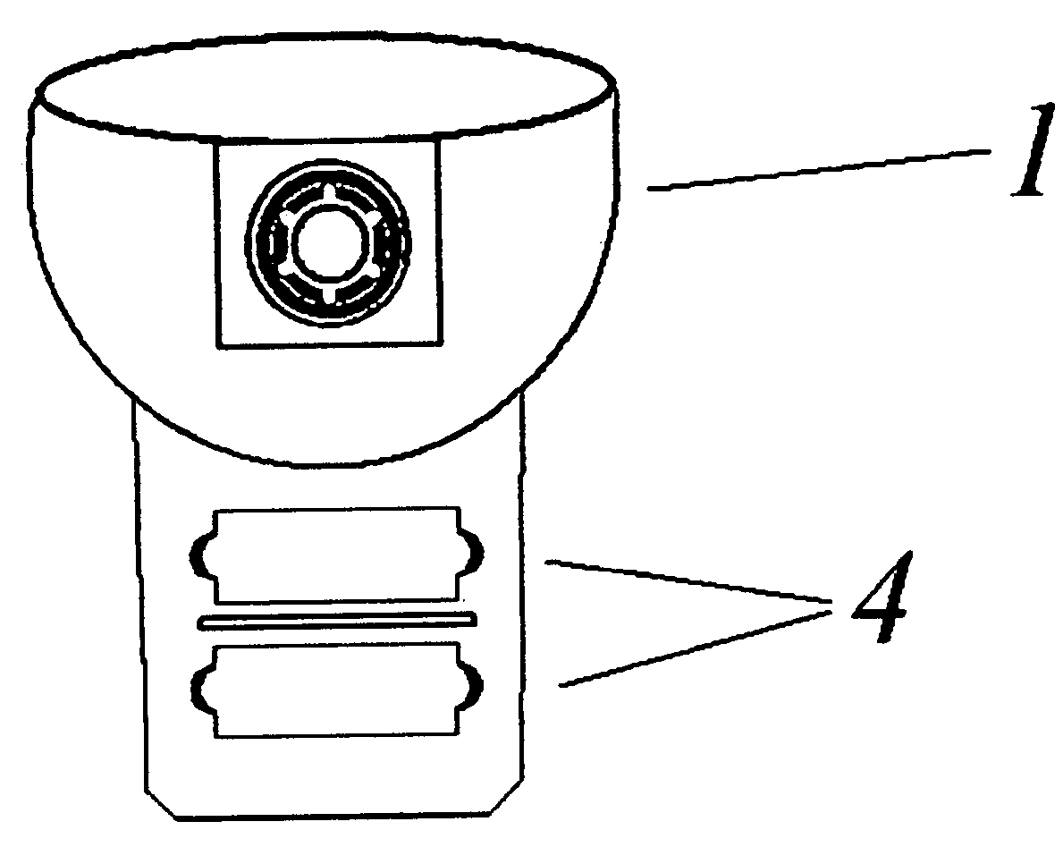
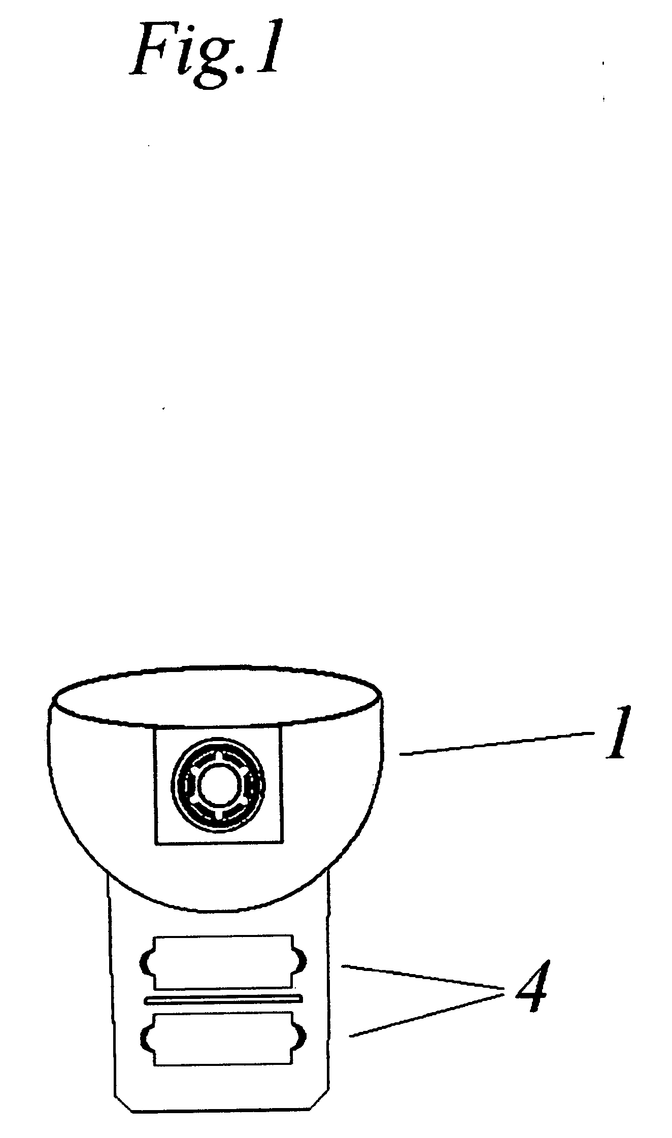
The ball throwing device (1) (FIG. 1) can be attached to a dog leash (2) (FIG. 2) or purposely made length of strap (3) (FIG. 10) using the purposely designed handle on the ball throwing device (4) (FIG. 1) or loop (15) (FIG. 10) or cord lock handle (12) (FIG. 19). With the ball throwing device (1) (FIG. 11) securely attached to a dog leash (2), the clasp end of the dog leash (5) can then be connected to a supplied retaining ring (6) located on the leash handle (7). The ball throwing device can be used for picking up a ball (8) (FIG. 6) hands free. This is achieved by placing the ball throwing device (1) over a ball (8) (FIG. 9) and pressing down firmly. The ball throwing device (1) fits neatly over the ball (8) and is able to hold the ball securely. The ball throwing device (1) (FIG. 5) could have an adjustable mechanism (9) or (FIG. 22) threaded knob (13) entering a threaded washer (14) for the purpose of controlling the distance that a ball (8) can be thrown. This can be achieved by rotating an adjuster knob (10) (FIG. 5) or (13) (FIG. 22), which is located on the outside edge of the housing cup hemisphere. The adjuster knob (10) (FIG. 5), which when rotated, causes a tapered inner plate (9) (FIG. 3) located on the inside of the housing cup (11) to revolve (FIG. 4) and can be used to decrease the overall size of the housing cup's (1) (FIG. 5) inner casing hemisphere (11). The threaded knob (13) (FIG. 22) can also be used to decrease the overall size of the inner casing hemisphere (11) by rotating the threaded knob (13) inward. With the ball throwing device (1) (FIG. 12) attached or incorporated into a dog lead (2) (FIG. 11) or strap (3) FIG. 10), the lead/strap can be swung in a forward/over arm throwing motion (FIG. 12), allowing the ball (8) to be projected. The projection of a ball is achieved by the ball releasing from the housing cup (1) through the use of centrifugal force. The distance a ball (8) can be thrown depends on which position the adjuster mechanism plate (9) (FIG. 14) is set. With the adjuster knob (10) rotated so that the tapered inner plate (9) (FIG. 3) is recessed and in the downward position, the tapered plate (9) falls behind the line of the inner casing hemisphere (11) (FIG. 14). The adjuster, whilst in the downward position, causes no interference with the ball (8) held within the housing cup (1) and enables the ball (8) to release and exit from the ball throwing device (1) with less force and momentum that is applied through the over arm swinging action of the leash (2) or strap (3) (FIG. 12). With the adjuster mechanism (9) (FIG. 4) in the upward position, the tapered inner plate (9) (FIG. 15) falls to the outside line of the housing cup's inner casing hemisphere (11). The tapered plate (9) (FIG. 5) whilst in this upward position, reduces the overall size of the inner casing hemisphere (11) which in turn, interferes and tightens the ball (8) (FIG. 9) against the housing cup's inner casing hemisphere (11) therefore holding the ball (8) inside the housing cup (1) more securely. The upward position of the tapered plate (9) (FIG. 5) also requires the user to apply more force to the over arm throwing action (FIG. 12) to enable the ball (8) to release and exit from the ball throwing device (1) with greater force and momentum, which in turn results in the ball (8) travelling further. The ball throwing device (1) (FIG. 6) is designed so that it can be held on the dog leash (2) whilst not in use, with or without the ball (8) inserted (FIG. 16). This feature enables the user to avoid having to place the dirty, messy ball (8) in their pocket or bag.

Description

BACKGROUND[0001]This invention relates to a ball throwing device that can be attached or incorporated into a dog lead or purpose made length of strap.[0002]When walking a dog in a country park or field etc. it is good fun to throw a ball for your dog to retrieve and hopefully return to you! However, this can be a strenuous activity on the human arm which can also involve the dog walker having to pick up a muddy, messy ball covered in dog saliva and when the game is over, the dog owner has to put the same messy ball in their pocket or bag!STATEMENT OF INVENTION[0003]According to the present invention there is provided a ball throwing device comprising a substantially semi-spherical ball housing cup and a strap / dog lead attachment means mounted on an outer surface of the ball housing cup such that, in use, with a strap / dog lead attached to the ball throwing device the device may be swung via the strap / dog lead enabling a ball placed in the ball housing cup to be projected. The ball th...

Claims


Application Information

Patent Timeline
IPC IPC(8): F41B3/04
CPCA01K15/025A63B2208/14A63B65/12
Inventor CATTLIN, BRETT
Owner CATTLIN BRETT
Why Eureka
Try Eureka