Interlocking Device for a Drawer Slide

a technology of locking device and drawer slide, which is applied in the direction of building locks, construction fastening devices, construction, etc., can solve the problems of high cost, high construction cost, and high construction cost, and achieve the effect of low cost and low pri

Inactive Publication Date: 2008-03-27
SUN CHAIN METAL IND
View PDF5 Cites 24 Cited by
  • Summary
  • Abstract
  • Description
  • Claims
  • Application Information

AI Technical Summary

Benefits of technology

[0011]The primary objective of the present invention is to provide a simply structured interlocking device for a drawer slide, and the secondary objective of the present invention is to provide a low cost and low price interlocking device for a drawer slide.

Problems solved by technology

The slide rails make it easier to pull and push the drawers, and the drawers can be pulled out completely, however, if the cabinet is accidentally inclined by improper use or external factors, such as earthquake, several drawers of the cabinet will be pulled out simultaneously.
At this moment, the position of center of the gravity of the cabinet will shift, as a result, the cabinet is likely to fall down to hurt the user or damage the articles inside the cabinet.
However, this conventional design is very complicated in structure and expensive.
Although the second conventional structure has been improved a lot, it still has too many components and its manufacturing and assembling process is still complicated.

Method used


Image

  • Interlocking Device for a Drawer Slide
  • Interlocking Device for a Drawer Slide
  • Interlocking Device for a Drawer Slide

Examples


Embodiment Construction

[0027]The present invention will be clearer from the following description when viewed together with the accompanying drawings, which show, for purpose of illustrations only, the preferred embodiment in accordance with the present invention.

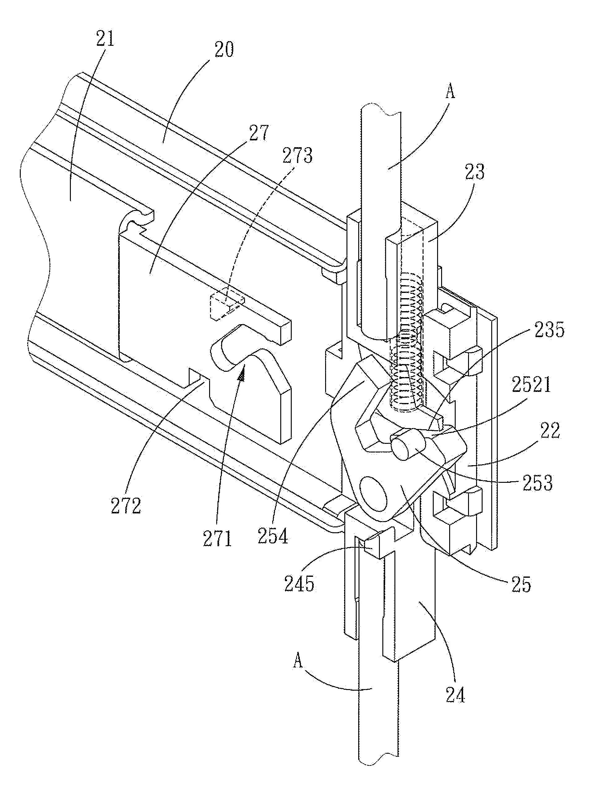
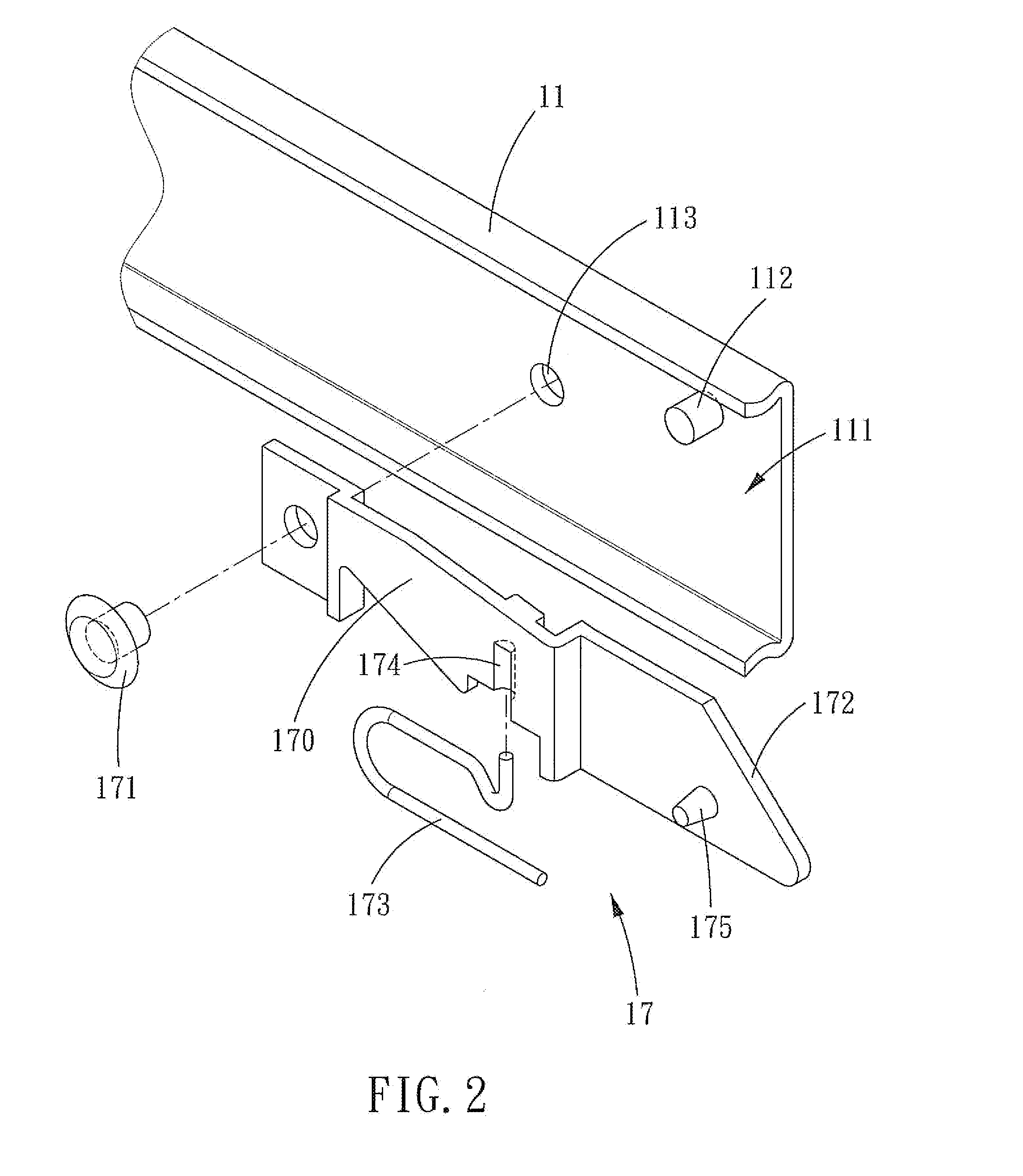
[0028]Referring to FIGS. 2-4, an interlocking device for a drawer slide in accordance with the present invention comprises: a fixed slide rail 10, at least one movable slide rail 11, a positioning block 12, a first locking member 13, a second locking member 14, a pivot control member 15, a spring 16, a control block assembly 17 and a plurality of connecting rods A. The interlocking device is disposed between the drawer and the surface of the cabinet. The first and second locking members 13, 14 are the same as the conventional structure in terms of design and technique; therefore, further explanations are omitted.

[0029]The fixed slide rail 10 is fixed to the surface of the cabinet and is provided with a receiving seat 101 on the drawer-receiving s...


PUM


Abstract

An interlocking device for a drawer slide is disposed at the end of a drawer and comprises a positioning block disposed at the end of the fixed slide rail, at least one moveable slide rail received in the fixed slide rail, a control block assembly, a first locking member, a second locking member, a pivot control member and a spring. The first and second locking members are pushed to clamp the pivot control member by the spring. The control block of the control block assembly is fixed at the end of the moveable slide rail. The drawer is used to move a control block on the slide rail, and then the guiding portion and the pushing block of the control block can pDush the pivot control member to move. Therefore, the interlocking device for a drawer slide is simple.

Description

BACKGROUND OF THE INVENTION[0001]1. Field of the Invention[0002]The present invention relates to an interlocking device for a drawer slide, and more particularly to an equipment disposed at the end of the drawer slide, which facilitates the interlocking of the interlocking device and simples the interlocking structure.[0003]2. Description of the Prior Art[0004]The pull and push design between a drawer and a cabinet is two opposite slide rails that are slideably mounted to each other for enabling the drawer to be movably disposed in the cabinet, and through the slide rails, the drawer can be pushed into or pulled out of the cabinet.[0005]With the time advances, the current drawer slide is further provided on the two slide rails with a stopping member, such as a protruding portion or a protruding block, which prevents the drawer from disengaging from and falling out of the cabinet when it is pushed. The drawer is normally defined with a relatively long longitudinal space for increasin...

Claims


Application Information

Patent Timeline
Patent Type & Authority Applications(United States)
IPC IPC(8): E05C7/06E05B65/46E05B65/464
CPCE05B65/464
Inventor RUAN, TENG YILEE, JOE
Owner SUN CHAIN METAL IND
Why Eureka
Try Eureka