
Electronic apparatus

a technology of electronic equipment and housing units, applied in the direction of electrical equipment, substation equipment, telephone set construction, etc., can solve the problems of poor operability, poor stability, poor stability, etc., and achieve the effect of improving the fixation precision of the housing uni

Inactive Publication Date: 2008-03-27
FUJITSU LTD
View PDF5 Cites 11 Cited by
  • Summary
  • Abstract
  • Description
  • Claims
  • Application Information

AI Technical Summary

Benefits of technology

[0012]The object of the present invention relates to an electronic apparatus that includes a housing unit of which the angle can be varied by a rotation mechanism, and is to improve the fixation precision of the housing unit fixed at a predetermined angle.
[0013]Further object of the present invention relates to an electronic apparatus that includes a housing unit of which the angle can be varied by a rotation mechanism, and is to improve the rotational operability of the housing unit and to improve the fixation precision of the housing unit fixed at a predetermined angle.
[0014]Yet further object of the present invention relates to an electronic apparatus that includes a housing unit of which the angle can be varied by a rotation mechanism, and is to improve the fixation of the housing unit fixed at a predetermined angle.

Problems solved by technology

However, in the case of the configuration adapted to generate sliding friction torque and clicking torque by exerting a load caused by a coil spring on a rotation mechanism using a two-shaft hinge (the above '499 publication), the stability thereof is poor because the load concentrates on the hinge and the fixation strength of a member supported by the two-shaft hinge is low or the fixation strength varies, etc.
In the case of the connecting structure including the leaf spring and the recessed portion (the above '289 publication), though the structure thereof is simple, the stability thereof is insufficient.
In the case of the setting mechanism that includes a thin bar to be manually operated between a vertically oriented posture (a 0-degree position) and a horizontally oriented posture (a 90-degree position) thereof and a recessed portion of the displaying unit and that holds an inserting angle, as a rotation locking setting and a releasing setting of the locking setting (the above '893 publication), the operability thereof is poor.
However, problems have arisen on the fixation that the holding angle for the rotating module is not constant (for example, dispersion of about ±0.7 degrees is present) and, therefore, a fitting gap is generated between a fixed unit and a displaying unit component in a closed state and an inclination of a displayed screen is generated in an opened state, etc.

Method used


Image

  • Electronic apparatus
  • Electronic apparatus
  • Electronic apparatus

Examples


first embodiment

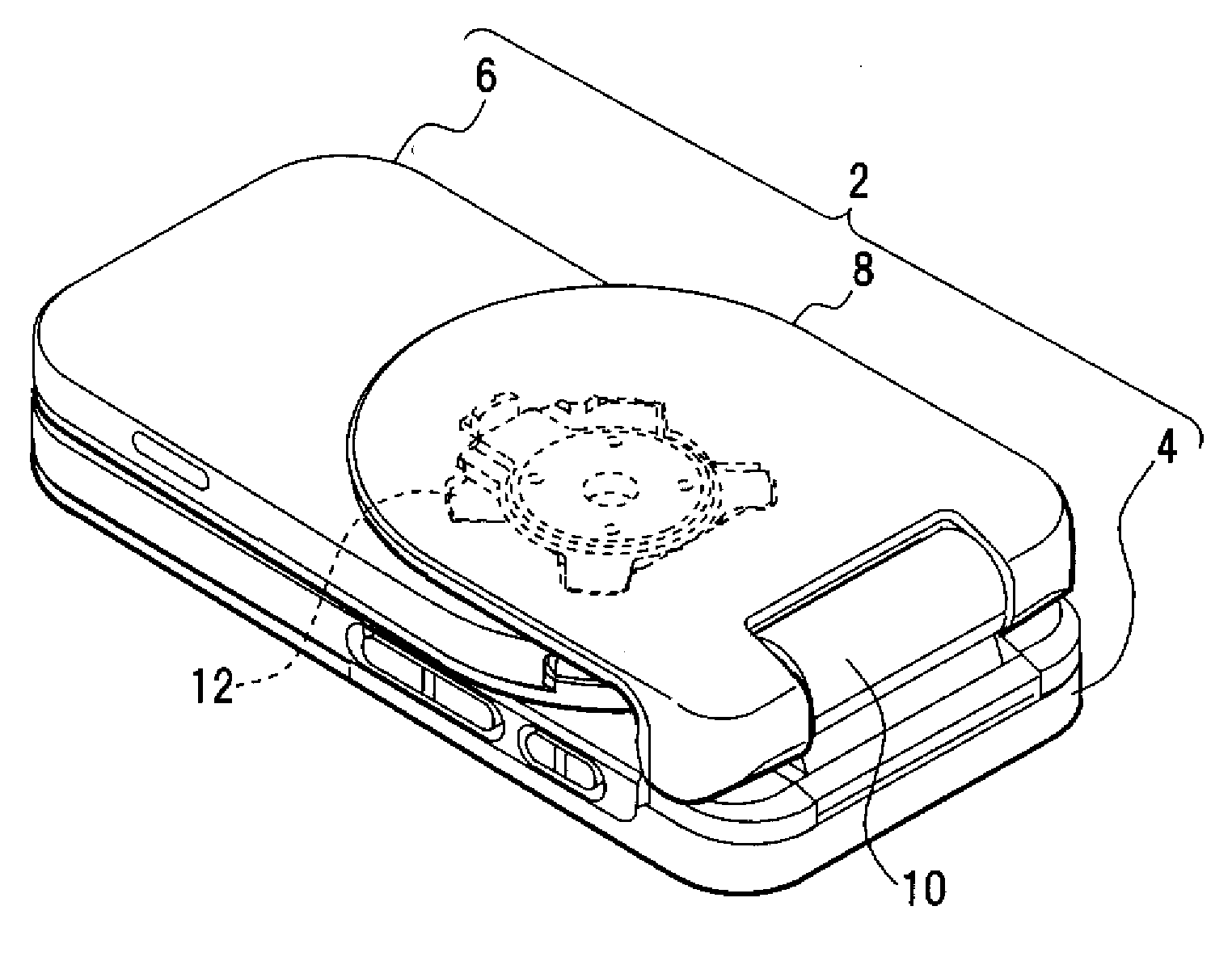
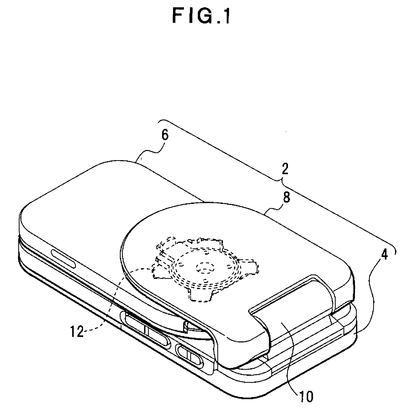
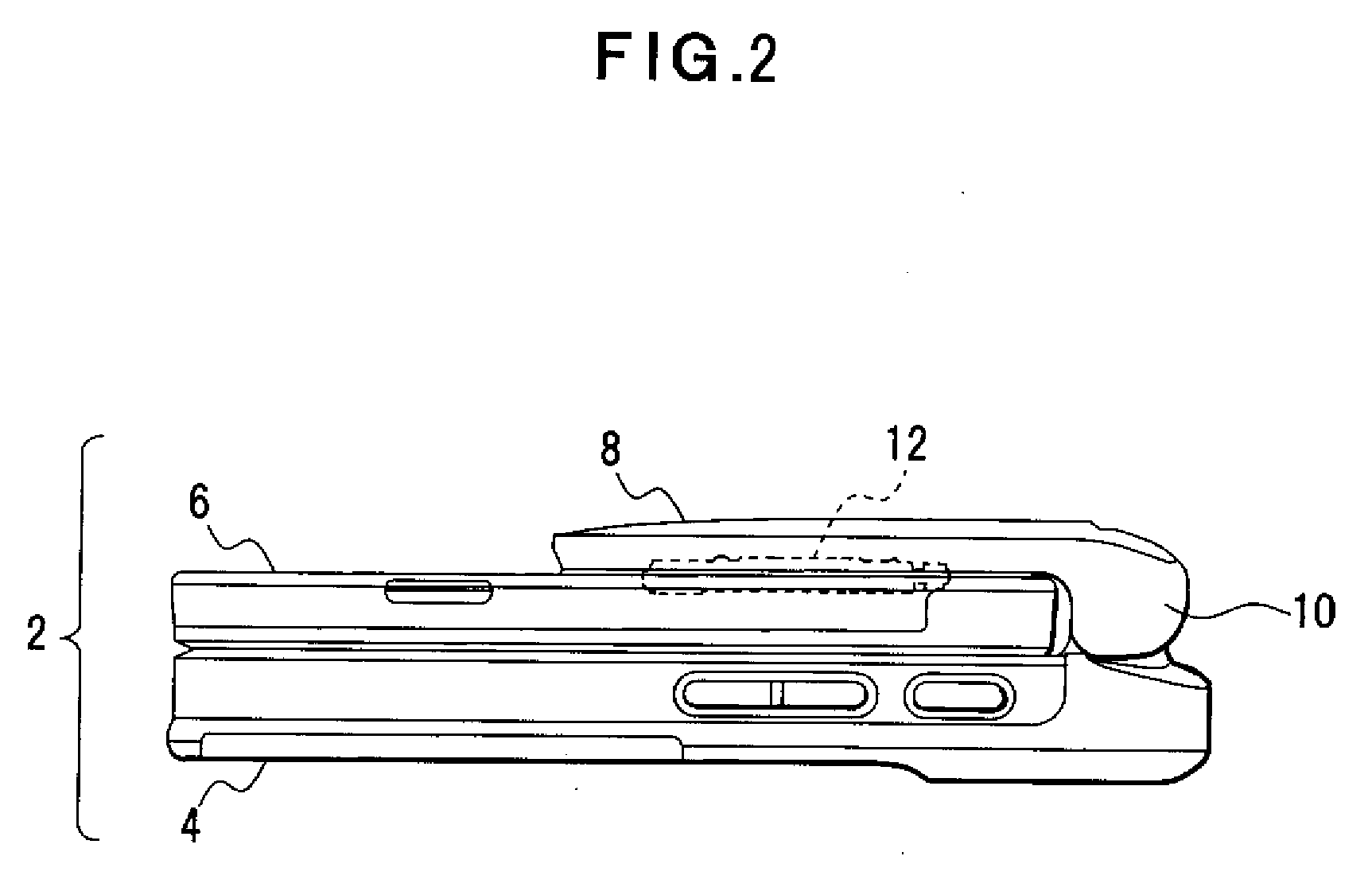
[0049]Description will be given for a first embodiment of the present invention referring to FIGS. 1 to 6. FIG. 1 depicts a perspective view of a portable terminal apparatus. FIG. 2 depicts a side view of a closed state of the portable terminal apparatus. FIG. 3 depicts a front view of an opened state of the portable terminal apparatus. FIG. 4 depicts a clockwise rotation (a counterclockwise rotation) of a movable housing unit of the portable terminal apparatus in the opened state thereof. FIG. 5 depicts a rear view of the portable terminal apparatus in the closed state thereof. FIG. 6 depicts a clockwise rotation (a counterclockwise rotation) of the movable housing unit of the portable terminal apparatus in the closed state thereof.

[0050]A portable terminal apparatus 2 is an example of an electronic apparatus including a plurality of movable units such as an opening and closing unit and a rotating unit and, as shown in FIGS. 1 and 2, includes a fixed housing unit 4 as a first housi...

second embodiment

[0092]Description will be given for a second embodiment of the present invention referring to FIGS. 20 and 21. FIG. 20 depicts a rotation locking mechanism. FIG. 21 depicts a modification of the rotation locking mechanism. In FIGS. 20 and 21, the components same as those in FIGS. 1 to 19 are given the same reference numerals.

[0093]Though the rotation locking mechanism 60 is adapted such that the locking pin 66 is movable by the restoring force of the coil spring 72 in the first embodiment, the locking pin 66 may be fixed to the movable housing unit 6. When the mechanism 60 is adapted such that the pin engaging portion 64 can be moved forward and backward by a coil spring as shown in FIG. 20, the same effect can be expected. In this case, a guiding shaft 124 is formed on the pin engaging portion 64 and a coil spring 126 is fitted with the guiding shaft 124.

[0094]According to the above configuration, by the engagement of the locking pin 66 installed in the movable housing unit 6 and t...


PUM


Abstract

The present invention relates to an electronic apparatus including a housing unit of which the angle can be varied by a rotation mechanism and is directed to improve the fixation precision of the housing unit that can be fixed at predetermined angles. The apparatus includes a supporting frame unit (movable arm unit), a rotation supporting unit (rotating module) installed on the supporting frame unit, a housing unit (movable housing unit) that is fixed on the rotation supporting unit and can be rotated by the rotation supporting unit, and a rotation locking mechanism that is installed away from the center of rotation of the rotation supporting unit and, when the housing unit is rotated to a predetermined angle, holds the supporting frame unit and the housing unit in a locked state.

Description

CROSS-REFERENCE TO RELATED APPLICATIONS[0001]This application is based upon and claims the benefit of priority from the prior Japanese Patent Application No. 2006-257319, filed on Sep. 22, 2006, the entire contents of which are incorporated herein by reference.BACKGROUND OF THE INVENTION[0002]1. Field of the Invention[0003]The present invention relates generally to an electronic apparatus such as a portable terminal apparatus including a rotatable displaying unit such as a liquid crystal display unit component, and more particularly, to an electronic apparatus including a movable housing unit that mounts a displaying unit and can be locked at predetermined angles.[0004]2. Description of the Related Art[0005]For an electronic apparatus such as a portable terminal apparatus including a rotatable displaying unit component, when the posture of the displaying unit component is adjusted by rotating the component from a vertically oriented posture to a horizontally oriented posture thereof...

Claims


Application Information

Patent Timeline
Patent Type & Authority Applications(United States)
IPC IPC(8): H04B1/38H04M1/00H04M1/02
CPCH04M1/0216H04M1/0247H04M1/0233H04B1/38
Inventor NAGAMINE, TOMOYUKIHORI, TETSUYAYAMAGUCHI, SHIGERU
Owner FUJITSU LTD
Learn More