Knob structure

Active Publication Date: 2008-04-03
ALTEK CORP
View PDF9 Cites 10 Cited by
  • Summary
  • Abstract
  • Description
  • Claims
  • Application Information

AI Technical Summary

Benefits of technology

[0007]It is one of objects of the invention to provide a knob structure in which less friction generates

Problems solved by technology

However, great contact area between the first protrusion a

Method used


Image

  • Knob structure
  • Knob structure
  • Knob structure

Examples


Example

[0015]Wherever possible in the following description, like reference numerals will refer to like elements and parts unless otherwise illustrated.

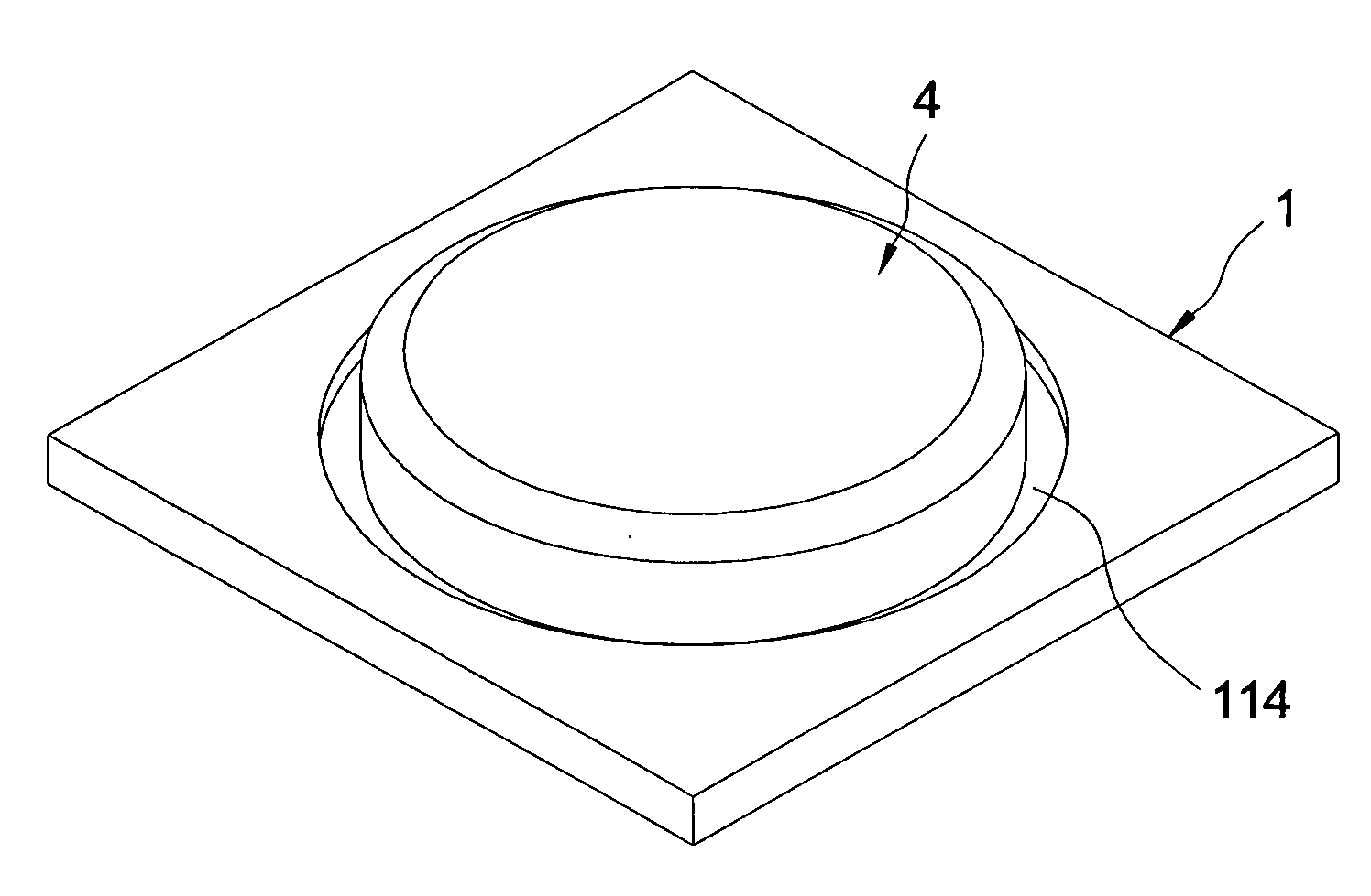
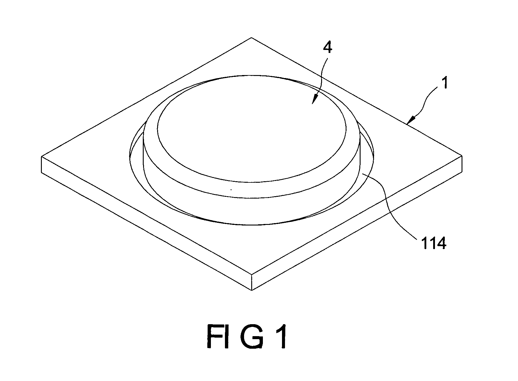
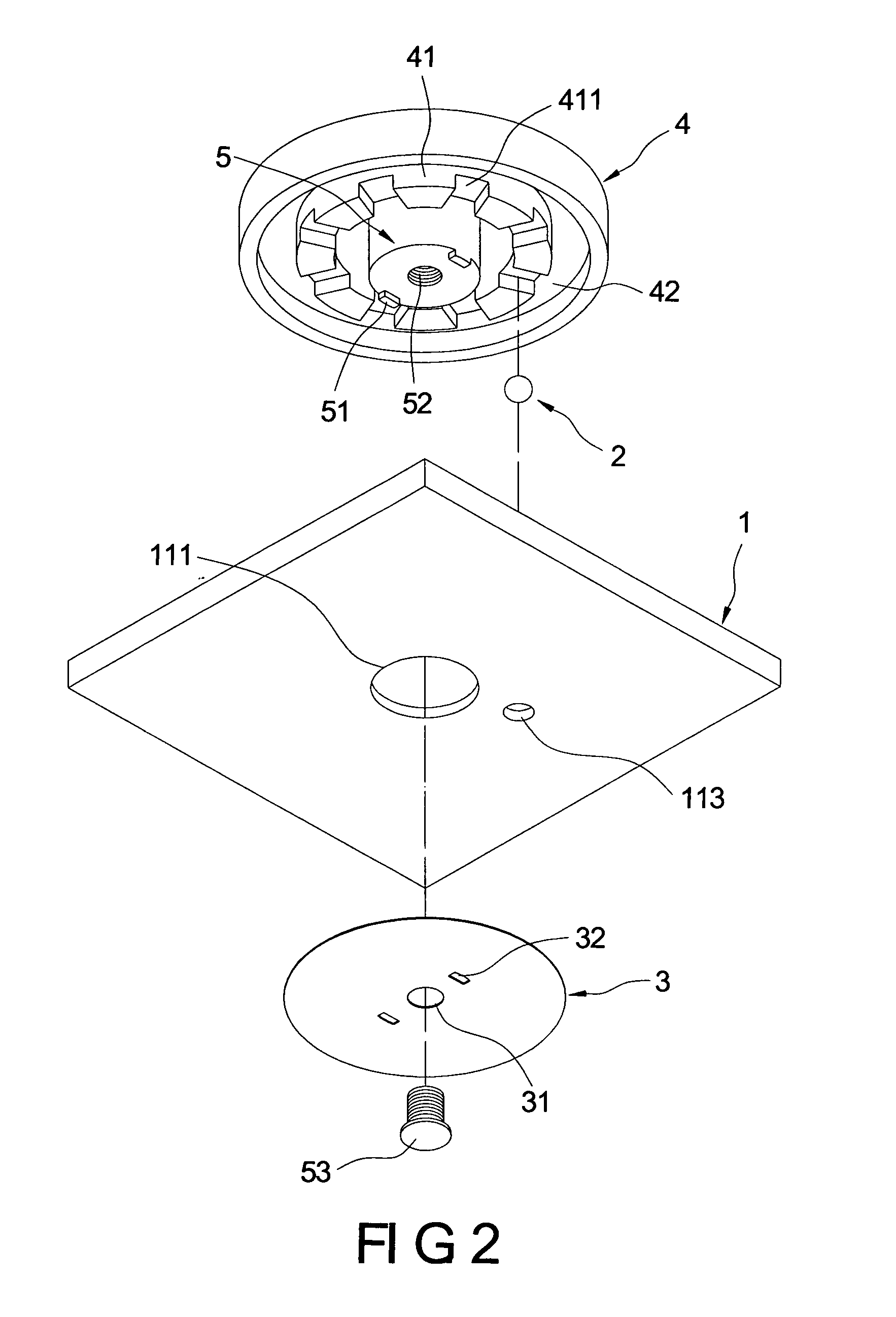
[0016]Referring to FIG. 1, FIG. 2, FIG. 3, FIG. 4A and FIG. 4B, the invention provides a knob structure mounted on an electronic device, in which the knob structure can be manually driven to switch its operation modes. The knob structure includes a holder 1, a steel ball 2, an elastic metallic piece 3, a swiveling element 4 and a connecting element 5.

[0017]The holder 1 is in form of flat plate and has a recess 11 at its top. The recess 11 has a positioning hole 111 through the whole recess 11, a guide ring 112 and a through hole 113. The positioning hole 111 locates at a center of the recess 11. The guide ring 112 forms around the positioning hole 111 on an inner wall of the recess 11 in a manner that a caved groove 114 forms between the guide ring 112 and the inner wall of the recess 11. The through hole 113 locates between the positioning...


PUM


Abstract

A knob structure includes a holder, a steel ball, an elastic metallic piece, a swiveling element and a connecting element. The holder has at least one through hole. The steel ball is slidably placed inside the through hole. The elastic metallic piece and the swiveling element reside at either sides of the holder. The elastic metallic piece slidably lies against the steel ball. The swiveling element has a sliding portion which has a plurality of notches spaced at intervals. The sliding portion slidably lies against the steel ball so that the steel ball slides into or out of the notches by turning the swiveling element. The steel ball has a smooth surface and is in point-to-point contact with the sliding portion and with the elastic metallic piece. Therefore, frictions therebetween are so small that no scraps generate due to the frictional operation.

Description

BACKGROUND OF THE INVENTION[0001]1. Field of the Invention[0002]The invention generally relates to a knob structure, and more particularly to a knob structure which creates a feeling of segments when turns.[0003]2. Description of the Related Art[0004]Taiwan patent No. I254957 (publication date: May 11, 2006) discloses an electronic device with a knob structure includes a casing with the knob structure thereon. The knob structure includes a first turning element having a first protrusion; a second turning element connecting to the first turning element in a way that the first turning element turns as the second turning element turns; a moving element which moves between the first and second turning elements and has a second protrusion matching the first protrusion for stopping the moving element in a idle position; and an elastic element which locates between the moving element and the second turning element and is used to return the moving element to the idle position by apply an el...

Claims


Application Information

Patent Timeline
IPC IPC(8): E05D7/00
CPCB60K37/06B60K2350/102G05G1/08Y10T16/506H01H19/11Y10T16/52G05G5/065B60K2370/126
Inventor HUANG, YU-CHENG
Owner ALTEK CORP
Why Eureka
Try Eureka