Assembling structure for rod to be fixed or detached with stand
Active Publication Date: 2022-11-03
LIAO TSUN CHI
View PDF2 Cites 1 Cited by
Summary
Abstract
Description
Claims
Application Information
AI Technical Summary
This helps you quickly interpret patents by identifying the three key elements:
Problems solved by technology
Method used
Benefits of technology
[0006]Therefore, after the upper clamp element and the lower clamp element are loosened, the rod can be quickly pulled out from the upper clamping space and the lower clamping space with less friction due to the presence of the bushing. When the column is re-inse
Problems solved by technology
However, stands of the prior art are not designed to be disassembled quickly for dynamically re-adjusting the position of the
Method used
Image
Click on the blue label to locate the original text in one second.
Reading with bidirectional positioning of images and text.
Examples
Embodiment Construction
[0011]Details and technical content, features, and effect of the present invention are given with the accompanying drawings below.
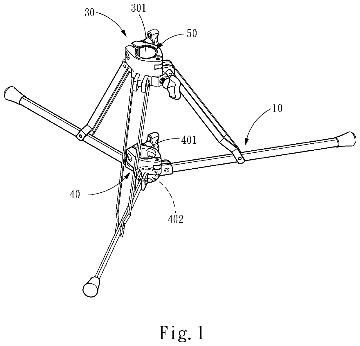
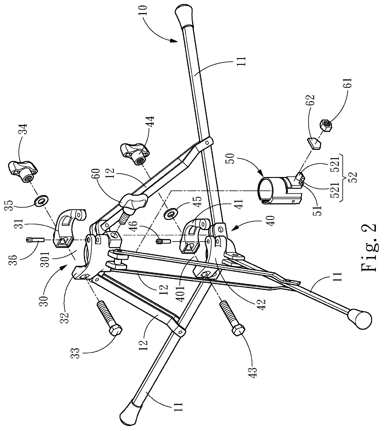
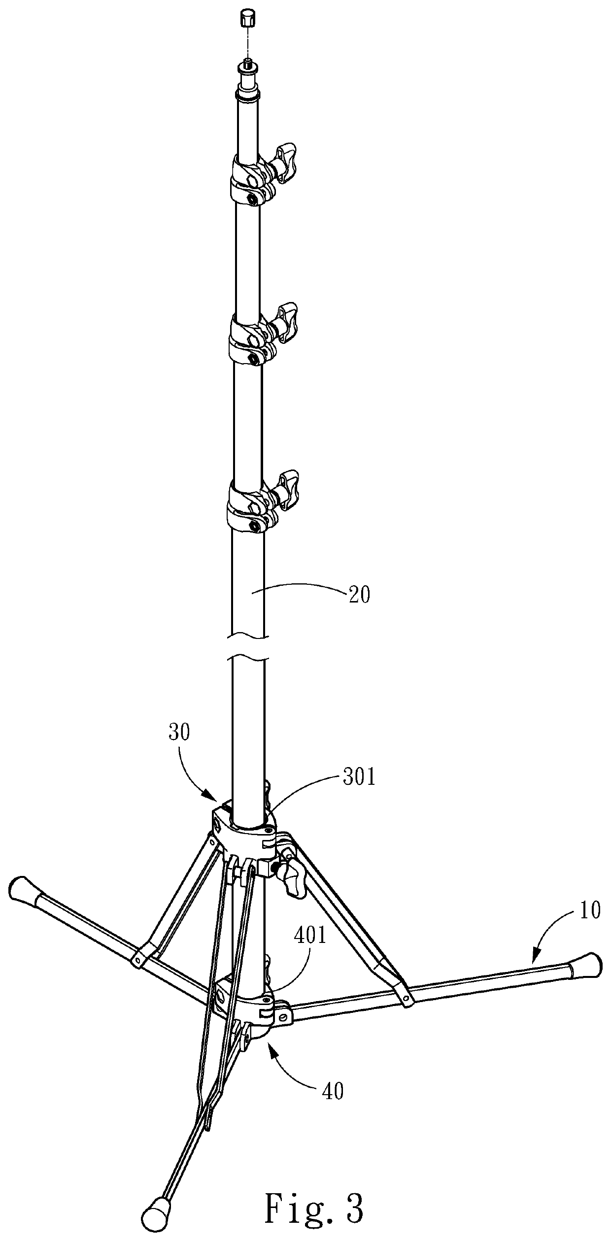
[0012]Referring to FIG. 1, FIG. 2 and FIG. 3, the present invention provides an assembling structure for a rod 20 to be fixed or detached with a stand 10, comprising an upper clamp element 30, a lower clamp element 40, and a bushing 50, wherein the upper clamp element 30 has an upper clamping space 301 and the shape of the upper clamping space 301 corresponds to the rod 20 in order to tightly clamp onto the stand 10. The stand 10 has three legs 11 and three support arms 12, wherein these three legs 11 are connected to the lower clamp element 40 individually; these three support arms 12 are individually connected to the upper clamp element 30 and those three legs 11 respectively. These three legs 11 can be adjusted to dispread to a designated opening angle based on the requirement and firmly set up on various terrain.
[0013]The lower clamp element 40 has a ...
PUM
Abstract
An assembling structure for a rod to be fixed or detached with a stand is provided, which includes an upper clamp element, a lower clamp element, and a bushing. The upper clamp element and the lower clamp element include an upper clamping space and a lower clamping space respectively. The shapes thereof correspond to the rod to tightly clamp the rod onto the stand. The lower clamp element includes a positioning structure that holds up the stand. The bushing is located between the upper clamp element and the stand body, so that the rod can be quickly pulled out from the upper and lower clamping space with less friction after the upper clamp element and the lower clamp element are loosened. When re-inserted, the rod is positioned through being held up by the positioning structure to meet the usage needs of fast withdrawal or positioning the rod.
Description
FIELD OF THE INVENTION[0001]The present invention relates to a stand structure of exhibition and studio equipment, and particularly to an assembling structure for a rod to be fixed or detached with a stand.BACKGROUND OF THE INVENTION[0002]For events such as singing, lectures, interviews, and shooting movies, various exhibition and studio equipment, e.g. microphones, lights, stereo systems, etc. will need to be fixed with the use of stands in order to record sound, set lighting, or play the audio at the appropriate positions. For example, stands being used to fix microphones at a selective height are disclosed in “Microphone stand adjusting structure” of U.S. Pat. No. 9,961,421 B2. To fix the position of a light, a stereo system, or an equipment, stands such as those disclosed in U.S. Pat. No. 10,767,807 B2.[0003]Stands of the prior art can be used to adjust and fix the height of the exhibition and studio equipment, whether it be lights, stereo systems, microphones, etc. The placemen...
Claims
Application Information
Patent Timeline
Application Date:The date an application was filed.
Publication Date:The date a patent or application was officially published.
First Publication Date:The earliest publication date of a patent with the same application number.
Issue Date:Publication date of the patent grant document.
PCT Entry Date:The Entry date of PCT National Phase.
Estimated Expiry Date:The statutory expiry date of a patent right according to the Patent Law, and it is the longest term of protection that the patent right can achieve without the termination of the patent right due to other reasons(Term extension factor has been taken into account ).
Invalid Date:Actual expiry date is based on effective date or publication date of legal transaction data of invalid patent.