Universal hockey puck

Active Publication Date: 2013-12-26
PONA STEVEN MICHAEL
View PDF0 Cites 2 Cited by
  • Summary
  • Abstract
  • Description
  • Claims
  • Application Information

AI Technical Summary

Benefits of technology

[0009]A feature of the present invention is a plurality of conically shaped apertures extending at an angle from one puck face to the opposing puck face. These conically shaped apertures channel the air as the puck is in flight so the puck stabilizes on a cushion of air. By stabilizing the puck on a cushion of air, the puck will travel straighter and with less wobble, thereby increasing the accuracy of the shots. Further by traveling on a cushion of air, less friction exists between the puck and the playing surface and, thus, enhances the flow of the puck over both ice and non-ice abrasive surfaces. Although the Bellehumeur puck has areas of open space within the puck, this space is only designed to decrease the weight of the puck without altering the overall puck size. The open spaces in the Bellehumeur puck are not designed to decrease the friction between the puck and a surface by channeling air through the spaces when the puck is traveling across the surface. The holes in the Vellines puck are cylindrical in shape and are primarily designed to reduce the overall weight of the puck. Although some air passes through the holes when the puck is inclined relative to the playing surface (i.e., one of the opposite faces is not parallel to the playing surface), the cylindrical shape of the holes and the vertical positioning of the holes relative to the opposite faces do not allow air to be channeled when the puck is travelling normally (i.e., one of the opposite faces essenti

Problems solved by technology

Although the Bellehumeur puck has areas of open space within the puck, this space is only designed to decrease the weight of the puck without altering the overall puck size.
Although some air passes through the holes when the puck is inclined relative to the playing surface (i.e., one of the opposite faces is not parallel to the playing surface), the cylindrical shape of the holes and the vertical positioning of the holes relative to the opposite faces do not allow air to be channeled when the puc

Method used


Image

  • Universal hockey puck
  • Universal hockey puck
  • Universal hockey puck

Examples


Example

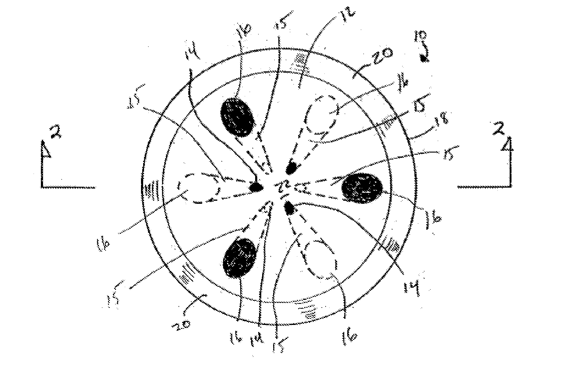
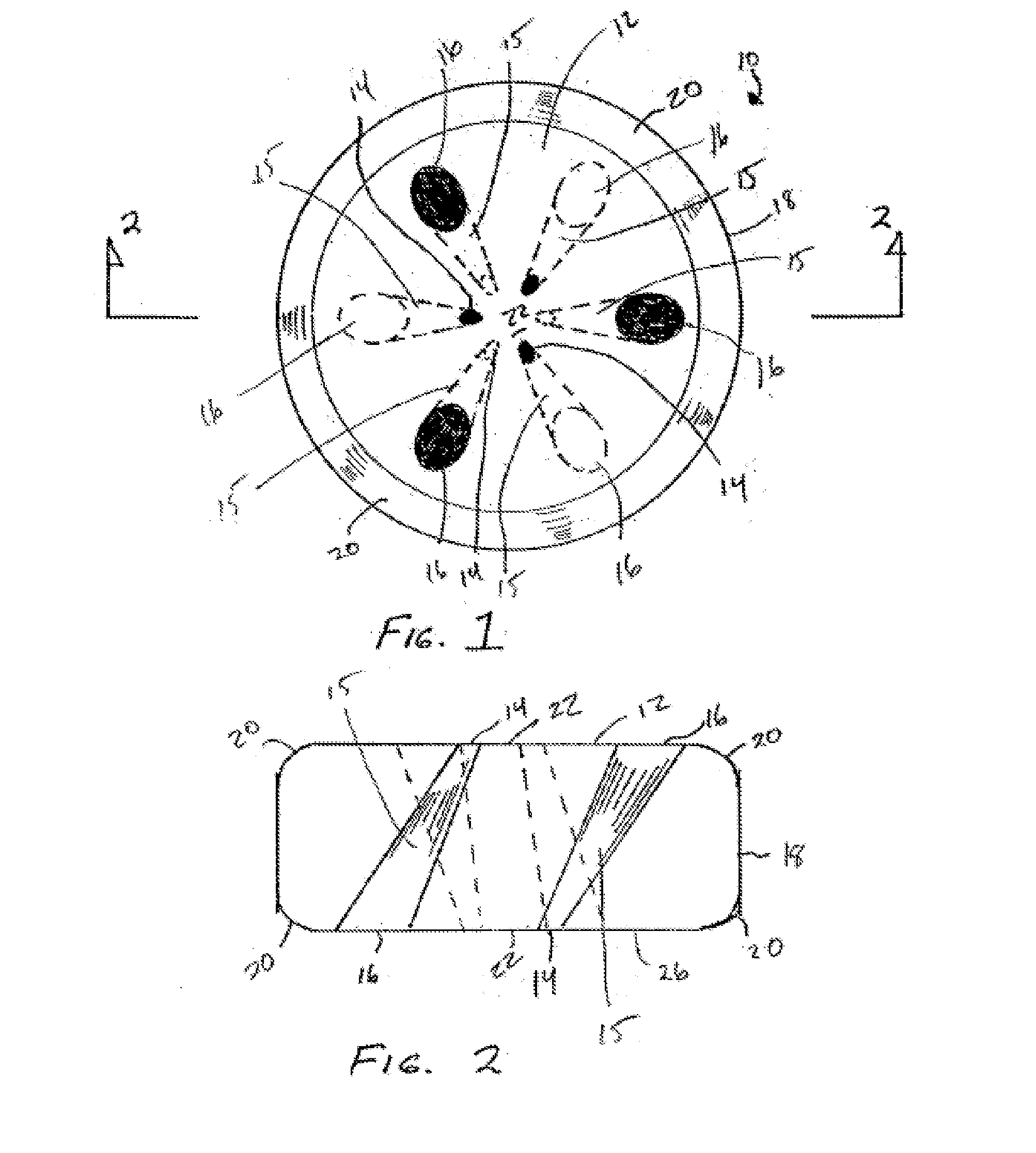
[0016]Referring to both FIGS. 1 and 2, a puck 10 in accordance with the present invention is shown having a first flat surface 12, a second flat surface 26 and an annular side surface 18. The puck 10 also includes a series of apertures 15. Each aperture 15 is conically shaped and has a large opening 16 at one end and a small opening 14 at an opposite end. Each aperture 15 extends from the one flat surface (either 12 or 26) to the other flat surface (26 or 12, respectively) of the puck 10. It is contemplated that, in the preferred embodiment, there be an even number of apertures with one half of the apertures positioned having their large openings flush with the second flat surface 26. In either case, the apertures are positioned so that the small openings are positioned closer to the center of the flat surfaces than are the large openings. In the preferred embodiment, there are six apertures, as shown in FIG. 1.

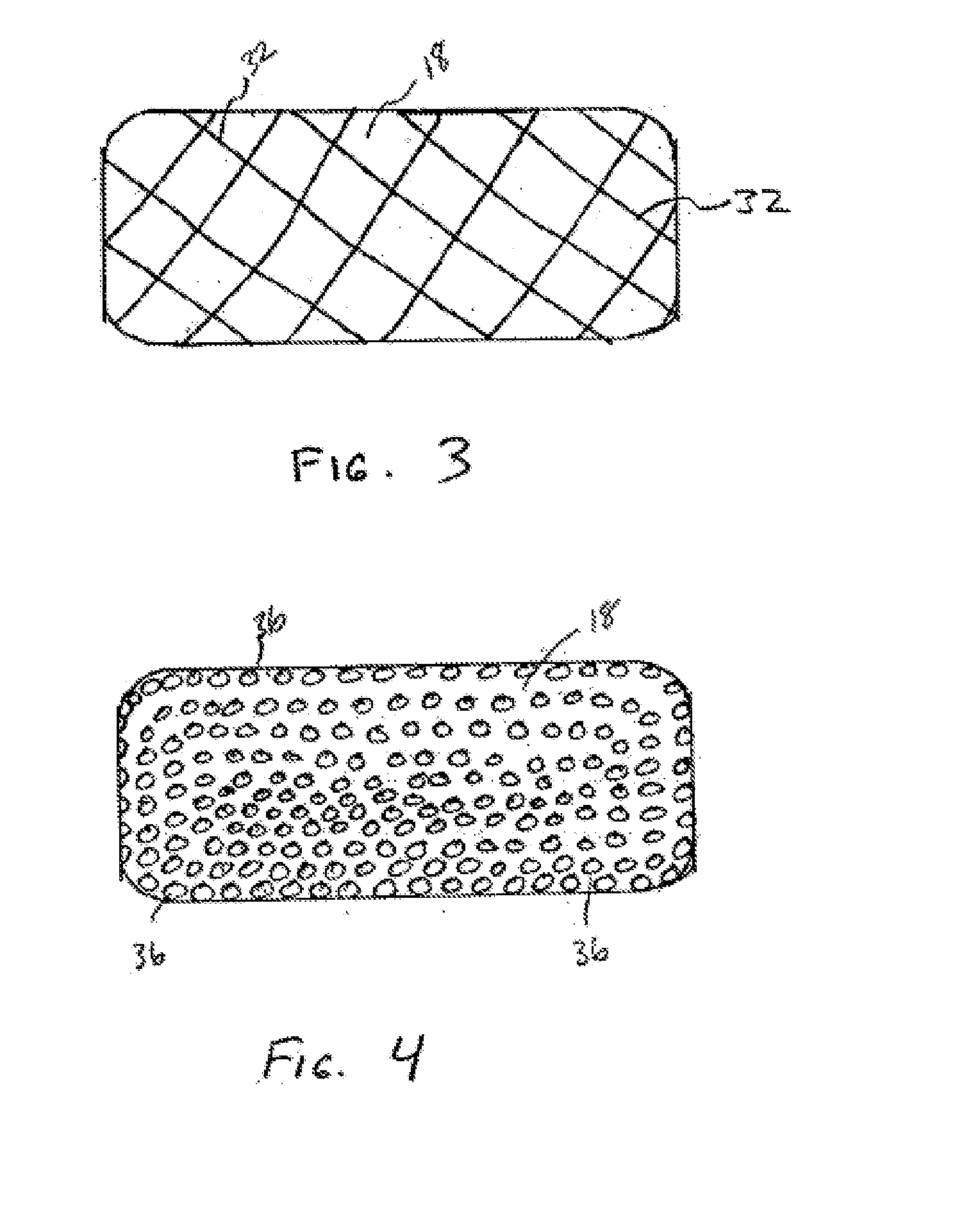
[0017]It is contemplated that the puck 10 be made from a molded composit...


PUM


Abstract

A hockey puck for use on both ice and non-ice surfaces. The puck has a plurality of conically shaped apertures extending at an angle from the top to the bottom of the puck to provide a stabilized cushion of air when the puck is in motion. The cushion of air reduces the friction between the puck and the surface, enabling the puck to remain at a high speed for a longer time period. The puck can be manufactured in a standard weight of 6 ounces for regular use or a lighter puck in the range of 4 to 4.25 ounces for junior hockey, street hockey or roller-hockey use. The annular side surface of the puck can be knurled or dimpled to enhance controllability and aerodynamics. Additionally, the corners of the puck can be rounded to reduce the effect of snow-plowing.

Description

FIELD OF THE INVENTION[0001]The present invention generally relates to sporting goods and in particular to hockey pucks for use on ice and non-ice surfaces.DESCRIPTION OF PRIOR ART[0002]Over the past several decades, the sport of ice hockey has increased in popularity. Originally, ice hockey was a sport limited to colder climate areas. This allowed for outdoor play on frozen ponds and lakes during the winter months. Because of the sport's popularity, many people desired to play hockey regardless of the weather. To achieve this, people used indoor ice rinks, where a suitable layer of ice could be maintained year round. However, ice rinks are expensive to build and maintain and therefore, they exist in limited numbers. In an effort to play more hockey, various forms of street hockey and roller-hockey were established. With street hockey, players use street shoes and no skates. In roller-hockey, in-line roller skates substitute for ice skates and allow a player to skate across a variet...

Claims


Application Information

Patent Timeline
IPC IPC(8): A63B67/14
CPCA63B67/14A63B2209/00A63B2225/01A63B2102/24A63B2102/22
Inventor PONA, STEVEN MICHAEL
Owner PONA STEVEN MICHAEL
Why Eureka
Try Eureka