Switch mode power supply controllers

Inactive Publication Date: 2010-09-30
POWER INTEGRATIONS INC
View PDF56 Cites 31 Cited by
  • Summary
  • Abstract
  • Description
  • Claims
  • Application Information

AI Technical Summary

Benefits of technology

[0034]In another, preferred, approach however, a switch of the type previously described is omitted and the input is connected to a signal following, for example, the voltage on an auxiliary winding of the magnetic device (transformer). For example an auxiliary winding may be coupled to the input of the sensing circuit via a potential divider. Such an arrangement has some advantages in that the decay signal may be dragged down by the sensing signal (auxiliary winding voltage), which allows the circuit to respond better to the sharp initial transients that can be present when the primary side switch first opens (in effect the potential divider and auxiliary winding behaving as a low pass filter). Another advantage of this latter approach in which a switch in series with the input is omitted, is that the timing of the knee point may be more accurately identified.
[0035]

Problems solved by technology

Typically such a power switching device comprises a bipola

Method used


Image

  • Switch mode power supply controllers
  • Switch mode power supply controllers
  • Switch mode power supply controllers

Examples


Example

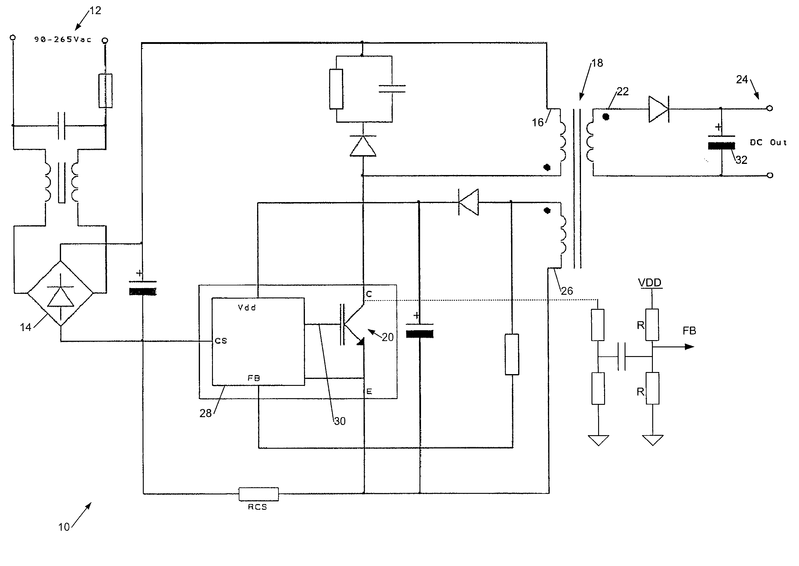
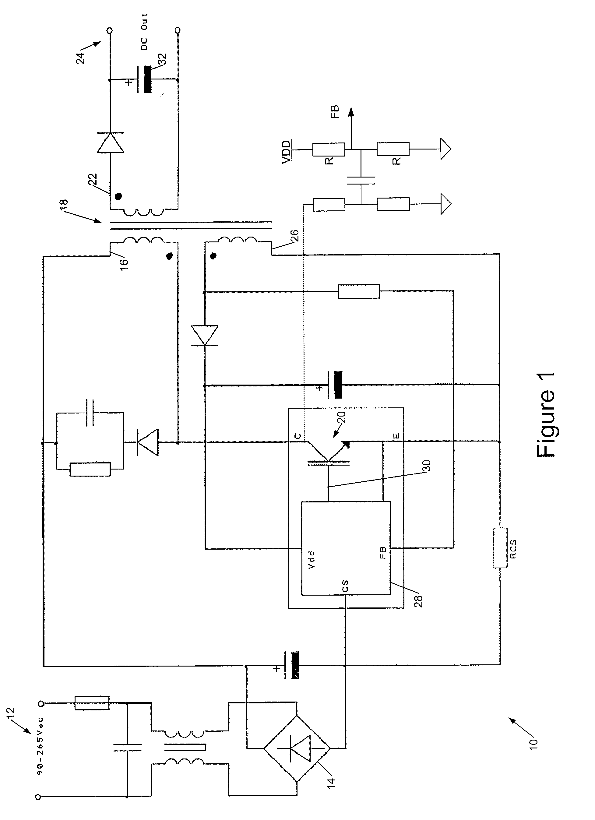
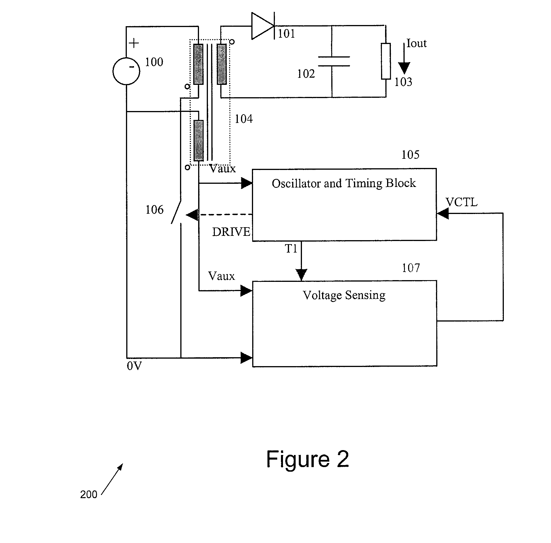
[0052]Broadly speaking we will describe an apparatus and a related method for measuring an output voltage from a primary side of a power converter. A winding on the power transformer, such as a primary or auxiliary winding, provides a waveform to a peak detector with defined decay characteristic. The peak detector voltage thus forms a tangent to a selected portion of the auxiliary winding waveform. A status signal from the peak detector indicates the time(s) when the tangent coincides with (and departs from) the auxiliary winding waveform, thus in DCM / CRM providing an estimated instant when the transformer secondary winding current has dropped to zero. The status signal controls a sample / hold circuit, which at that instant captures a voltage reflecting a secondary voltage of the transformer, such as a voltage from the primary or an auxiliary winding of the transformer. In CCM essentially the same technique may be employed to determine when the (primary side) power switching device h...


PUM


Abstract

This invention relates to SMPS controllers employing primary side sensing. We describe a system for identifying a knee point in a sensing waveform, at which the output voltage of the SMPS may be sampled accurately on the primary side. The system identifies the knee point, broadly speaking, by tracking a portion of a power transformer voltage waveform, and samples the voltage waveform at the knee point to determine the SMPS output voltage. In preferred embodiments this technique is implemented using a circuit akin to a decaying peak detector, providing a timing signal indicating detection of the knee point. Sample/hold and error amplifier circuits may be employed to achieve output voltage regulation.

Description

CROSS-REFERENCE TO RELATED APPLICATIONS[0001]This application is a continuation-in-part of U.S. patent application Ser. No. 12 / 405,618, filed Mar. 17, 2009, which is a continuation of U.S. patent application Ser. No. 11 / 445,473 filed Jun. 1, 2006 corresponding to issued U.S. Pat. No. 7,567,445 B2, issued Jul. 28, 2009, which claims priority under 35 U.S.C. 119 from United Kingdom Application No. 0610211.5 filed 23 May 2006, which applications and patents are incorporated herein by reference in their entirety.FIELD OF THE INVENTION[0002]This invention generally relates to a switch mode power supply (SMPS) controllers and to related methods. More particularly it relates to SMPS controllers employing primary side sensing to detect in a sensing waveform, at which point the output voltage of the SMPS may be sampled on the primary side.BACKGROUND TO THE INVENTION[0003]Broadly speaking in a switch mode power supply a magnetic energy storage device such as a transformer or inductor is used ...

Claims


Application Information

Patent Timeline
IPC IPC(8): H02M3/335
CPCH02M3/33523
Inventor COULSON, DAVID ROBERTPIPER, JOHANGARNER, DAVID MICHAEL
Owner POWER INTEGRATIONS INC
Why Eureka
Try Eureka