Torque limiting mechanism with lock bushing

Active Publication Date: 2012-03-08
WILSON GREATBATCH LTD
View PDF6 Cites 32 Cited by
  • Summary
  • Abstract
  • Description
  • Claims
  • Application Information

AI Technical Summary

Benefits of technology

[0007]The present invention provides a torque limiter device that is designed to secure a threaded fastener such as a bolt, screw or nut to a specified torque value. Fasteners are often used in surgical applications such as to secure an orthopedic implant or other device within the body. The present invention can be used as a hand held instrument or may be utilized as a power driven device. The torque limiting mechanism of the present invention primarily comprises a housing, an elongated body with a plurality of springs or washers, a threshold bearing, a torque gear, and a series of ball bearings. These components are arranged circumferentially about the elongated body or shaft such that the washers or springs compress the threshold bearing against the torque gear. The torque gear, which is connected to the elongated body or shaft, compresses against the ball bearings, which in turn compress against an internal surface of the housing. The mechanism further comprises a lock bushing and retaining ring that reside at the proximal end of the elongated body. The lock bushing and retaining ring ensure proper alignment and minimize lateral movement of the components within the device, particularly the elongated shaft with respect to the series of ball bearings and the torque gear. Such improvements in alignment of the elongated shaft with respect to the torque gear afforded by the lock bushing and retaining ring contribute to the increased accuracy of the present invention.
[0008]Furthermore, the structural design of the torque limiter device of th

Problems solved by technology

This misalignment of the torque gear with respect to the longitudinal shaft within these prior torque limiters creates a frictional interference within the device.
Such misalignments results in inaccurate torque outputs as well as increased mechanical wear of the device.
In addition, these prior art torque limiter devices are typically constructed with a plurality of intricate and complex components that are intended to fit and work precisely together.
However, the complexity and increased number of components generally result in tolerance stack up and other structural misalignments.
The cumul

Method used


Image

  • Torque limiting mechanism with lock bushing
  • Torque limiting mechanism with lock bushing
  • Torque limiting mechanism with lock bushing

Examples


Example

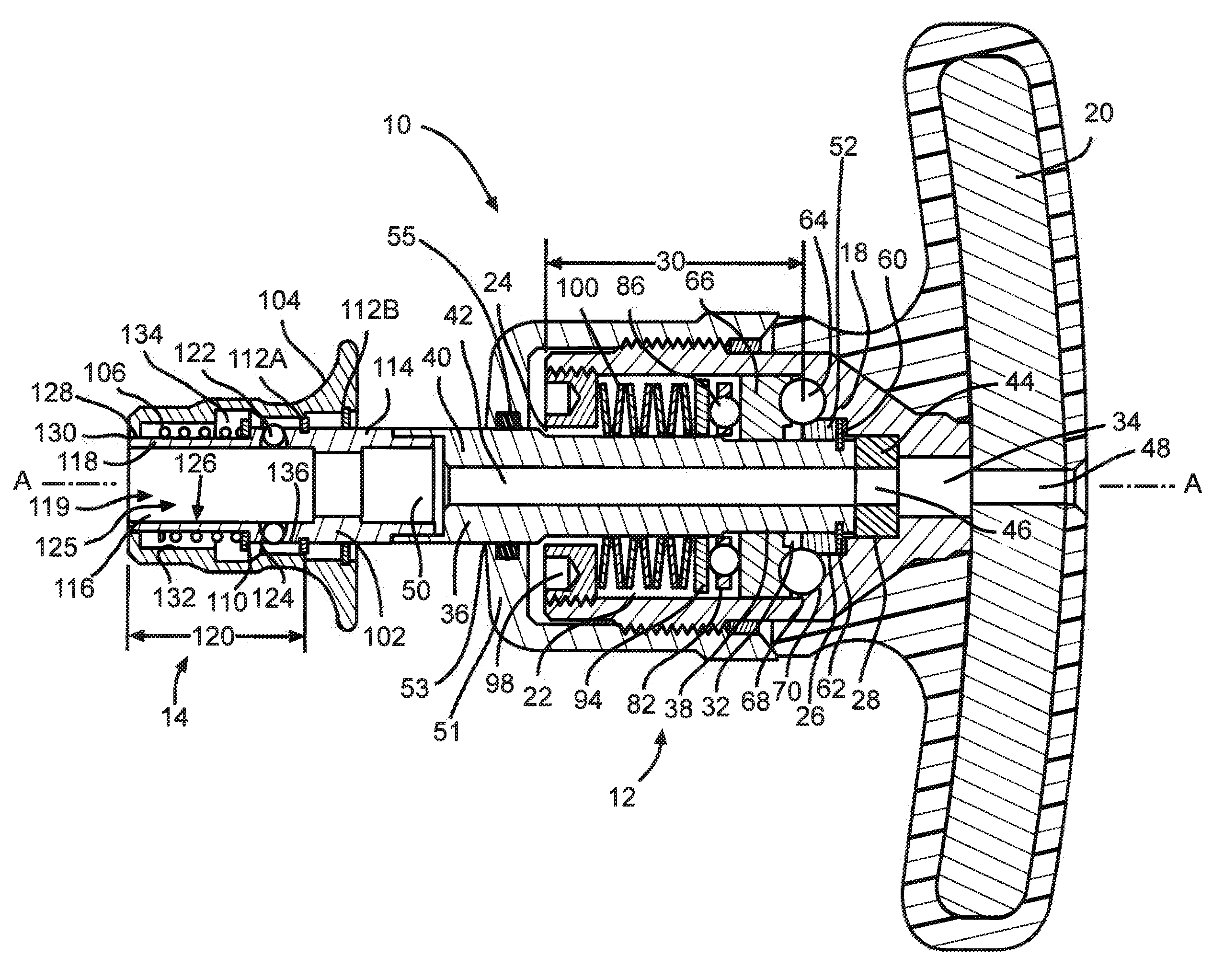
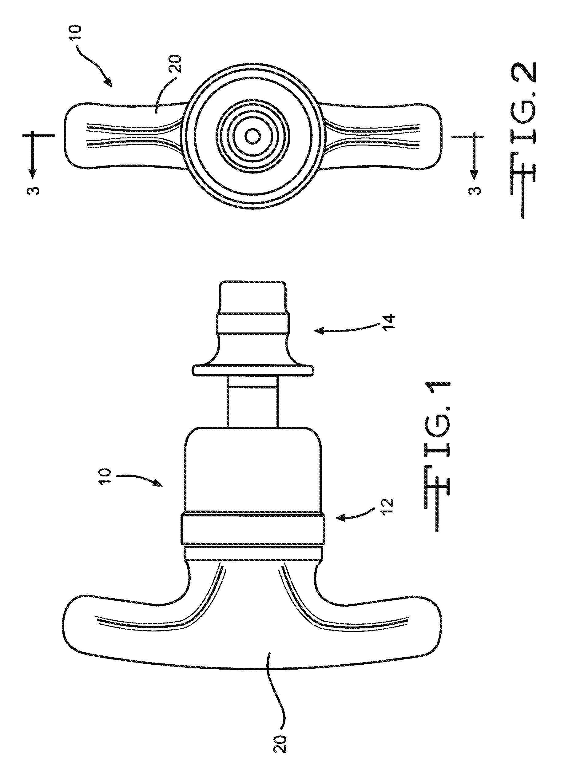
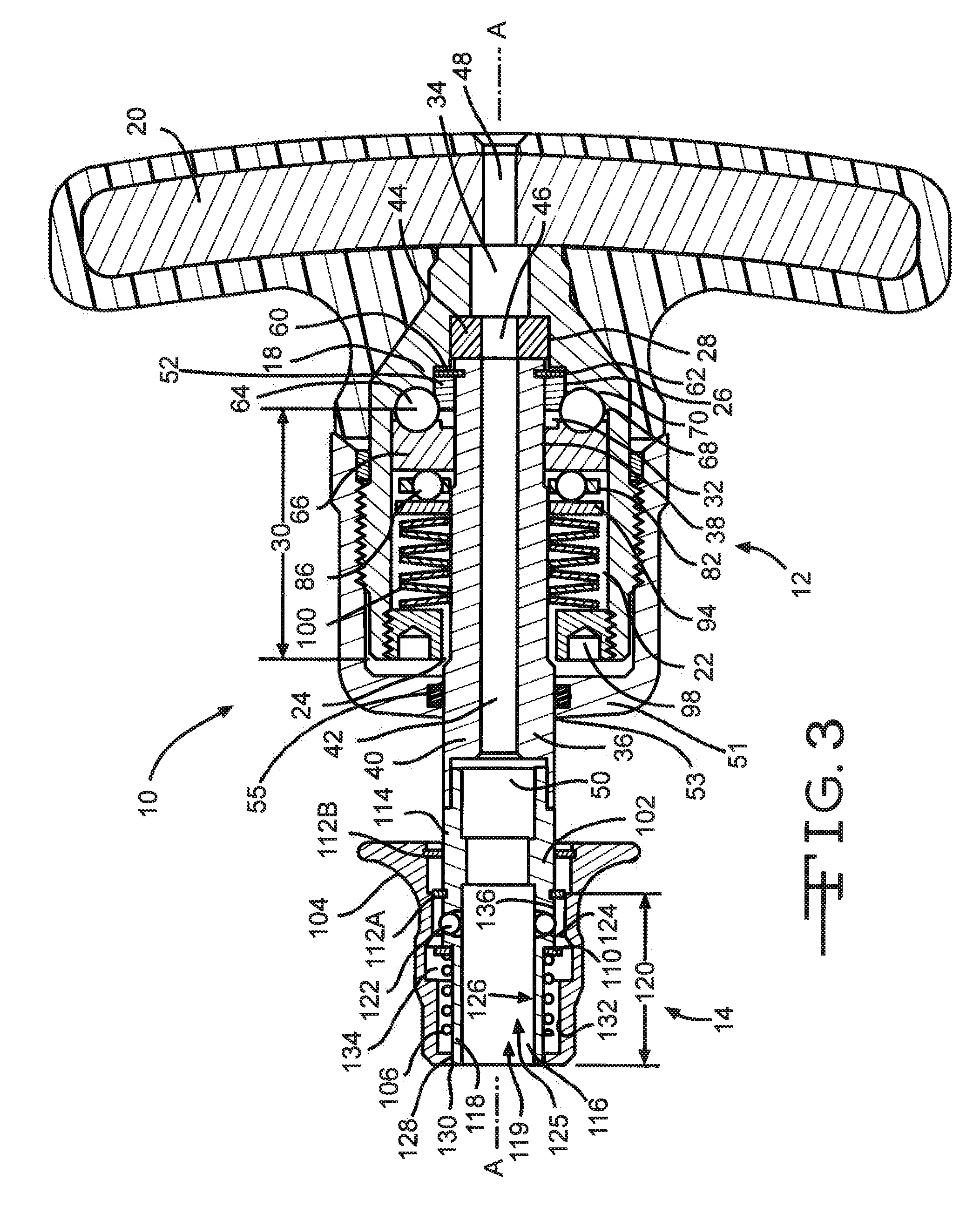
[0020]Referring now to the figures, FIGS. 1-5, 5A and 6-8 illustrate embodiments of a torque limiter device assembly 10 of the present invention and associated components. The device assembly 10 comprises a torque limiter device 12 and an adapter 14 connected therebetween. The torque limiter device 12, having a distal end portion spaced apart from a proximal end portion, further comprises a torque limiting mechanism 16 therewithin. The torque limiting mechanism 16 resides within a housing 18 of the device 12. A handle portion 20 is fluidly connected to the proximal end of the housing 18 of the device 12.

[0021]As shown in FIG. 3, the housing portion 18 has a first cavity 22 with a first cavity opening 24 that extends from the distal end of the housing 18. The first cavity 22 transitions into a second cavity 26, and the second cavity 26 further transitions into a third cavity 28. The second cavity 26 is proximal of the first cavity 22 and the third cavity 28 is proximal of the second ...


PUM


Abstract

A torque limiting mechanism used for securing fasteners is described. The torque limiting mechanism consists of a shaft, a torque gear having a plurality of ball bearings, a threshold bearing and a variable force applying subassembly. The torque limiting mechanism further consisting of a lock bushing and retaining ring placed circumferentially around the proximal end of the shaft. The lock bushing and retaining ring reduce structural misalignments and increase the accuracy of the device.

Description

CROSS REFERENCE TO RELATED APPLICATIONS[0001]This application claims priority to U.S. provisional application Ser. No. 61 / 379,938, filed on Sep. 3, 2010.FIELD OF THE INVENTION[0002]This invention relates to surgical tools for aiding in installing orthopedic prostheses, and more specifically, to an improved torque limiter device for installing orthopedic implants.BACKGROUND OF THE INVENTION[0003]Torque limiting devices have been utilized in various medical applications. For example, torque limiter devices have been used to fasten nuts and bolts that are utilized to secure surgical implements such as orthopedic implants. As such, it is important that these devices enable the user to apply a consistent and exacting amount of torque. The delivery of an exact amount of torque is critical in securing an implant or other surgical implement in the correct position without causing damage to the implant and the patient.[0004]Prior art torque limiting devices are typically constructed with tor...

Claims


Application Information

Patent Timeline
IPC IPC(8): B25B23/143F16D7/08
CPCB25B23/1427A61B17/8875B25B23/141A61B2019/301F16D7/08F16D43/206F16D1/112A61B2090/031
Inventor LANDOWSKI, STEVE
Owner WILSON GREATBATCH LTD
Why Eureka
Try Eureka