
Portable Pet Restraint Device

Inactive Publication Date: 2013-04-18
SHARP TIM +1
View PDF0 Cites 5 Cited by
  • Summary
  • Abstract
  • Description
  • Claims
  • Application Information

AI Technical Summary

Benefits of technology

The patent describes an animal restraint device that can be easily attached and detached from carpet and is designed for small dogs. It consists of two stems, one inside the other, with a platform to maintain stability on the floor. The second stem also allows for easy coupling with an elastic strap for securing the pet to a limited area of the floor. The strap is able to rotate horizontally around the outer stem, allowing the pet to move in a limited area. The device can be easily removed from the carpet with a knob and setscrew, and can be placed in different locations to minimize carpet wear. It is portable and can be used in homes, offices, and while traveling.

Problems solved by technology

One common problem to these known methods and devices is a lack of portability.
For example, a fence becomes a fixed improvement to the land and cannot be readily and practically moved when traveling with the pet.
A crate or cage is often bulky and cumbersome to move, and when in-place offers a very restricted area for the pet that is overly confining for long periods of time.
Fastening a leash to a heavy piece of furniture is portable, compact, easy to travel with, but leaves the owner at the mercy of the type of furniture found in the hotel room or other venue: Further, many dogs, for example, can overpower the weight of the piece of furniture, thus dragging the furniture around, damaging the property or injuring itself in the process.
Each of the above devices require a stake or similar appendage to pierce the ground, and accordingly, is ill-suited for indoor use because there is no teaching in these references of how the ground-inserting member can penetrate the floor without permanent damage to the floor, or to the insertion member, or both.
Further, these devices are inoperable for insertion into a floor because it would destroy the floor, and even if that were not objectionable, they would further be inoperable as there would be insufficient friction between the relatively thin floor (as compared to the surface area offered by inserting the same in the earth) and the insertion member.
Although Etkin's device works well as an indoor restraint, it requires the weight of the panel in combination with a short length of lead to restrict the dog to an area defined by the panel, and such a device is, accordingly, large, bulky, and cumbersome.
This is exasperated as the pet size increases and it quickly becomes impractical for larger dogs.
One limitation of this device is that it overly confines the animal to a very small area, and forces the animal to stand in its own excretions, which is at best inhumane and more likely negligent—thus, Capperrune's device must only be used for extremely short period's of time and under constant supervision, thus drastically reducing the usefulness of the device for restraining a pet.
However, such weighted members have inherent limitations and many excited or strong dogs can easily pull or drag the weighted member across the surface.

Method used


Image

  • Portable Pet Restraint Device
  • Portable Pet Restraint Device
  • Portable Pet Restraint Device

Examples


third embodiment

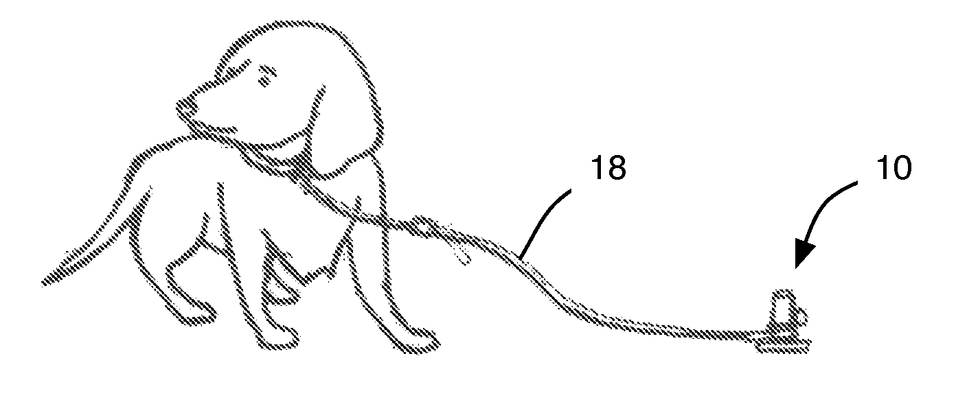
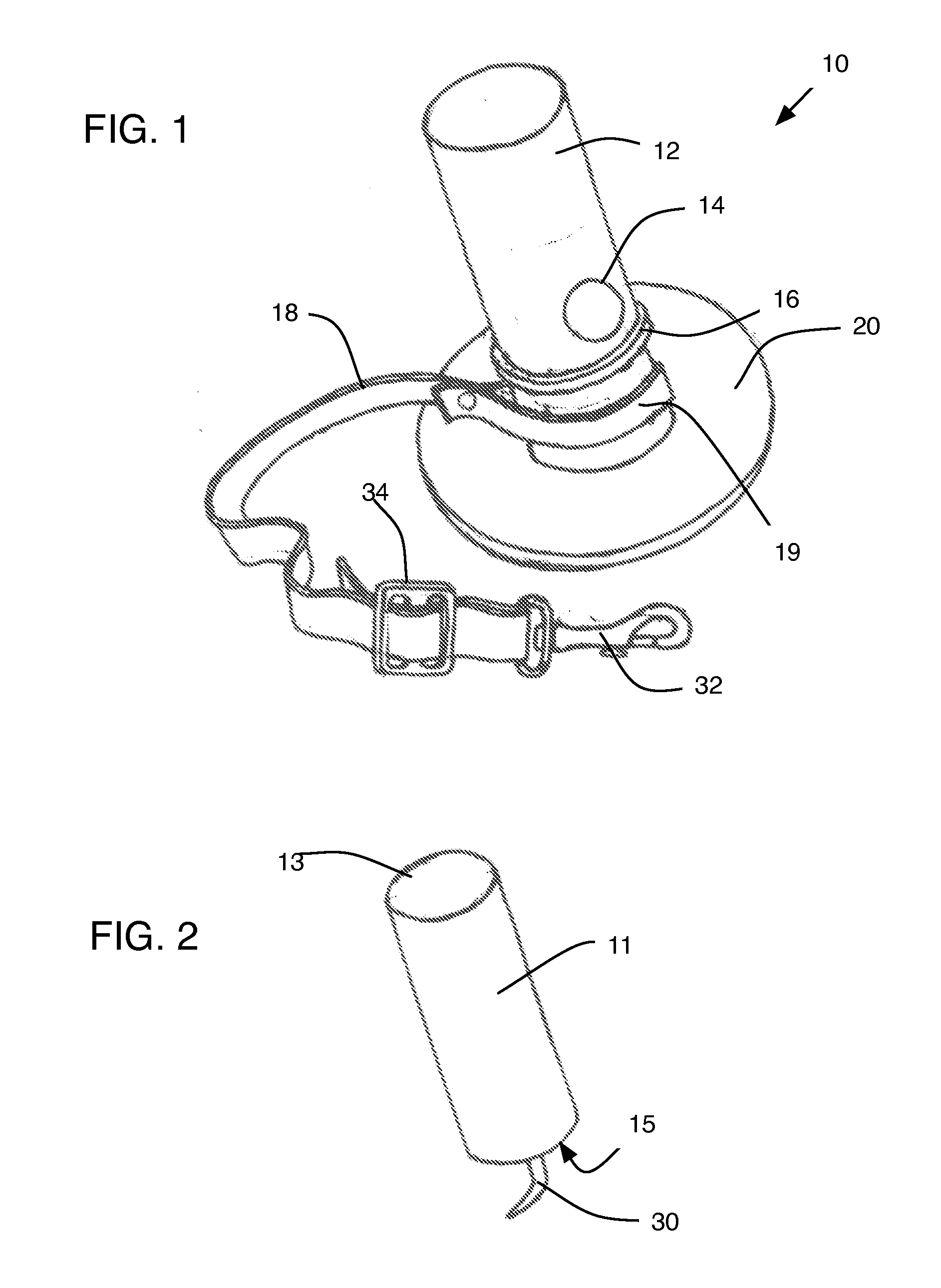
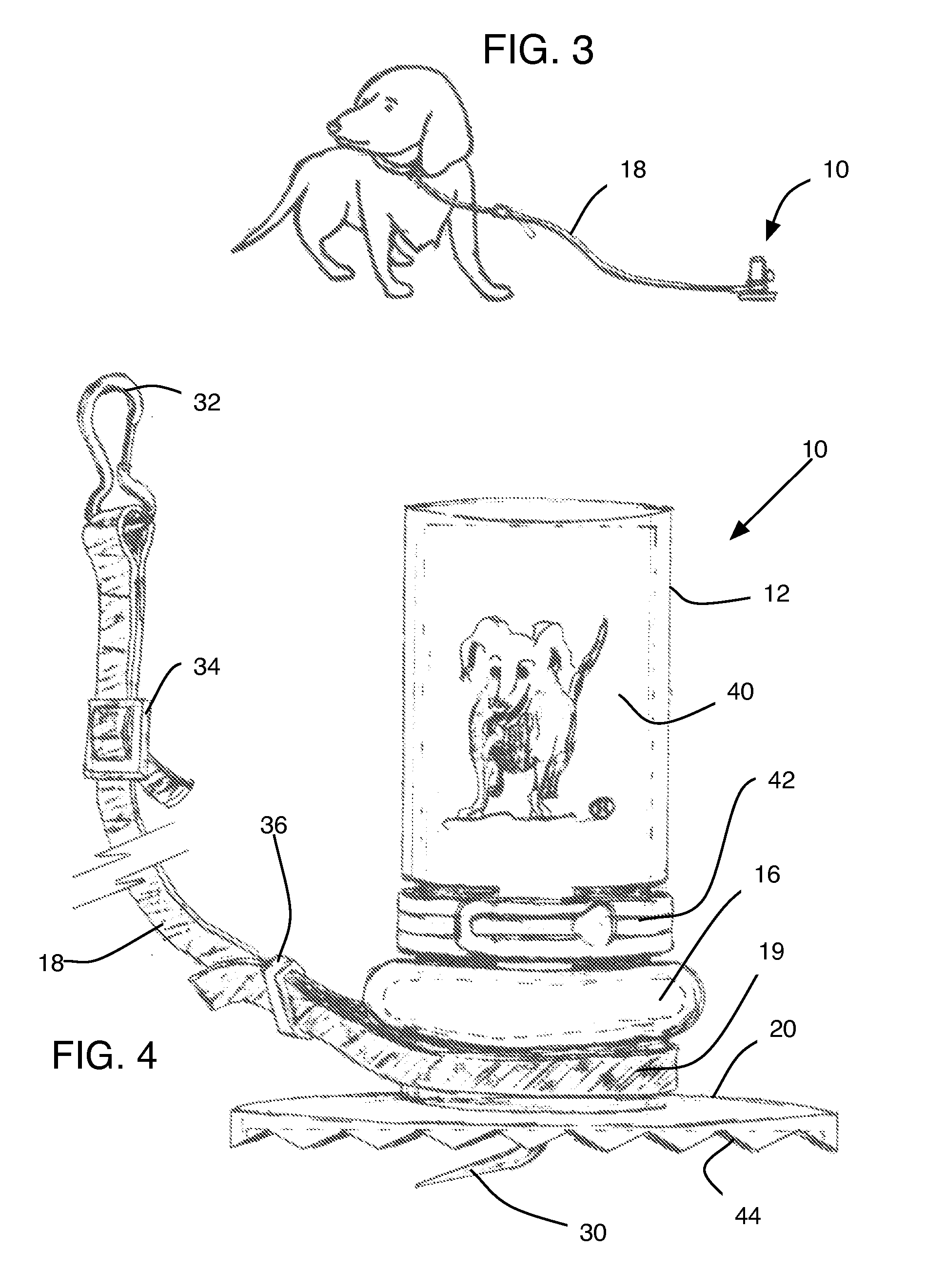
[0059]In one contemplated and preferred embodiment, for example as FIGS. 1, 2, 3, 5, and 6 illustrate, the present invention consists of a restraining device 10 for pets. The device includes a first stem 11 having a top portion 13 (which can be adapted to receive accessories such as bowl 80, for example). The first stem also includes a floor engaging means arranged at a second end 15, which consists of either a bent, central pin 30 or a suction cup (discussed in relation to a third embodiment, below). The first stem further comprising a base member 20 having bottom surface having any combination of the following, a serrated edge 44, a rubber or other rubber-like high-friction material, a hook and loop fastener material or a plurality of pins.

[0060]The device further includes a second stem 12 adapted to selectively slide over the first stem, the second stem includes a retaining lip 16 and a means for selectively coupling the second stem to the first stem 11. This coupling means compr...

first embodiment

[0066]A second preferred embodiment, as FIG. 4 shows, includes the same or similar construction as the first preferred embodiment previously described. Additionally, the second stem includes a logo placement area 40, which is well-suited for marking the device 10 with a logo or advertisement. A retaining ring clip 42 selectively pinches the second stem over the top of the first stem. A retaining feature 16 consists of a rubber ring. Common features to the first embodiment are not described here in the interest of brevity.

[0067]A third preferred embodiment, for example, as FIGS. 7-9 show, includes a base 20 having a suction cup 50 for releasably coupling to a smooth floor surface (such as tile, linoleum, wood, cork, vinyl and the like). Other features and elements are similar to the first two embodiments and, accordingly, are not repeated in detail here. Of note, in this embodiment the base includes a suction device 50 that includes a release lever 52 that aids in evacuating the spac...

fourth embodiment

[0074]FIG. 14 illustrates an accessory for the fourth embodiment discussed above. The main disc body 73 receives a screw post 78, which slides over the knob 86. The screw post can be made of a hard rubber-like material that deforms slightly as it is inserted over the knob, but reforms and matches the contour of the knob. A bowl 80 including an attachment portion 83 mates to the screwpost 78. The tether (not shown in FIG. 14) attaches as per normal and operates normally, but the pet now has a bowl for drinking water, and this bowl is less likely to spill because it is fixably attached to the device 73, which is attached to the carpet, for example (this bowl 80 would also work when the disc body 73 is in the smooth floor attachment 60 of FIGS. 10-13, for example).

[0075]With specific reference to FIGS. 15-25, this preferred embodiment of a restraining device 10 for temporarily coupling a domestic animal to a floor includes a post 86 comprising a retaining lip 16 and tether-resting chan...


PUM


Abstract

A restraining device for temporarily coupling a domestic animal to a floor includes a post having a retaining lip and tether-resting channel. A locking plate positions on the post below resting channel. A first and second locking wing hingeably mount to the post and are operable from a closed position to an open position, and each locking wing includes a top-mounted locking feature retainer to selectively engage the locking plate. And, the first and second locking wing each respectively further comprising a plurality of carpet-engaging spikes. A smooth floor attachment device selectively couples to the first and second locking wings. The smooth floor attachment device includes a base having oppositely disposed pair of retainers on a top portion and an adhesive strip or other mechanism for selectively attaching the base to the floor on a bottom portion.

Description

PRIORITY CLAIM[0001]The present application claims benefit under 35 USC Section 119(e) of U.S. Provisional Patent Application Ser. No. 61 / 546,691 filed on Oct. 13, 2011: The present application is based on and claims priority from this application, the disclosure of which is hereby expressly incorporated herein by reference.FIELD OF THE INVENTION[0002]This invention relates generally to restraining and confining device and, more particularly, to portable physical restraint devices adapted for domestic pet use, particularly for indoor use.BACKGROUND[0003]Domestic animals, particularly pets that reside inside the home of an owner, need to be restrained at times for various reasons including safety of the pet and convenience of the owner.[0004]Various attempts to confine pets to a specific physical area inside or outside a home include the use of an animal run, a crate, a chain coupled to a post or other immovable object, fencing a portion of the yard, using “baby gates” to restrict ac...

Claims


Application Information

Patent Timeline
IPC IPC(8): A01K1/04A01K5/01
CPCA01K5/01A01K1/04
Inventor SHARP, TIMSHARP, LAUREL
Owner SHARP TIM
Learn More