Compression head stabilizer

a stabilizer and compression head technology, applied in the field of concrete block molding apparatus, can solve the problems of affecting the stability of the compression head of the existing block machine, so as to minimize the lateral movement of the compression head or press

Inactive Publication Date: 2007-05-15
WOMACK JOHNNY
View PDF7 Cites 4 Cited by
  • Summary
  • Abstract
  • Description
  • Claims
  • Application Information

AI Technical Summary

Benefits of technology

[0004]It is therefore an object of the invention to provide a device and method for minimizing the lateral movement of a compression head or press.
[0005]A further object of the invention is to provide a device and method for minimizing the front-to-back movement of a compression head or press.
[0006]A further object of the invention is to provide a kit adapted to fit onto a concrete block fabricating machine for minimizing the lateral movement and / or front to back movement of a compression head of the machine.
[0007]A further object of the invention is to provide a device and method for improving the precision of a block machine for locating a mold plunger of a compression head into a mold box.
[0008]Another object of the invention is to provide a device and method for decreasing damage to a block machine caused by the imprecise engagement of a mold plunger and mold box of the machine.

Problems solved by technology

However, guide rails alone have proven to be inadequate at decreasing compression head play.
Specifically, for example, the amount of undesired movement of the compression head of some existing block machines is approximately ¼ of an inch.
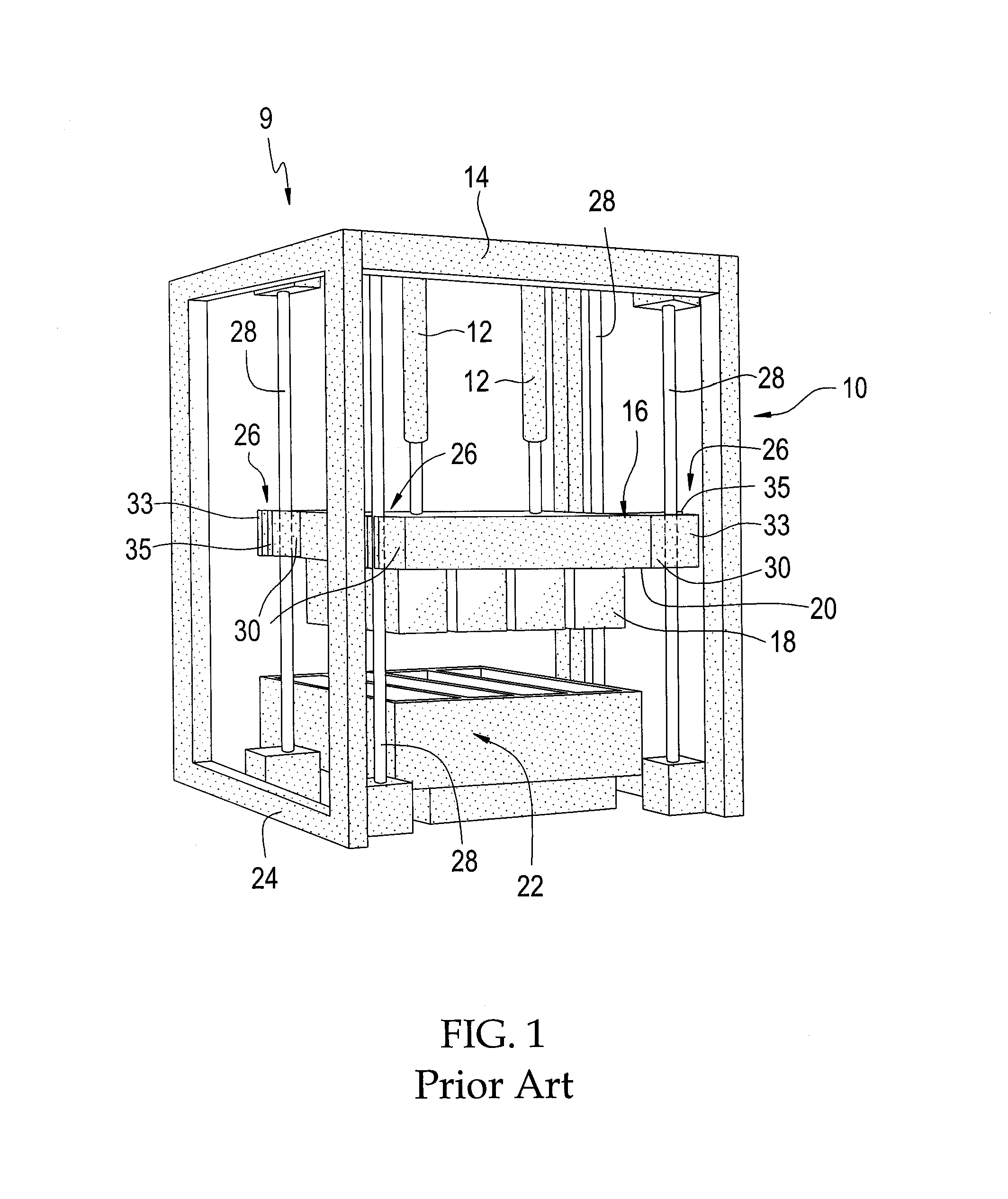
Consequently, it is not uncommon for the plunger head to strike the mold box where it was not intended to strike thereby damaging both the plunger head and the mold box, including the mold box end liner and mold box core.
Additionally, overtime, the cylinders that actuate the compression head can be so damaged as to require replacement.

Method used


Image

  • Compression head stabilizer
  • Compression head stabilizer
  • Compression head stabilizer

Examples


example

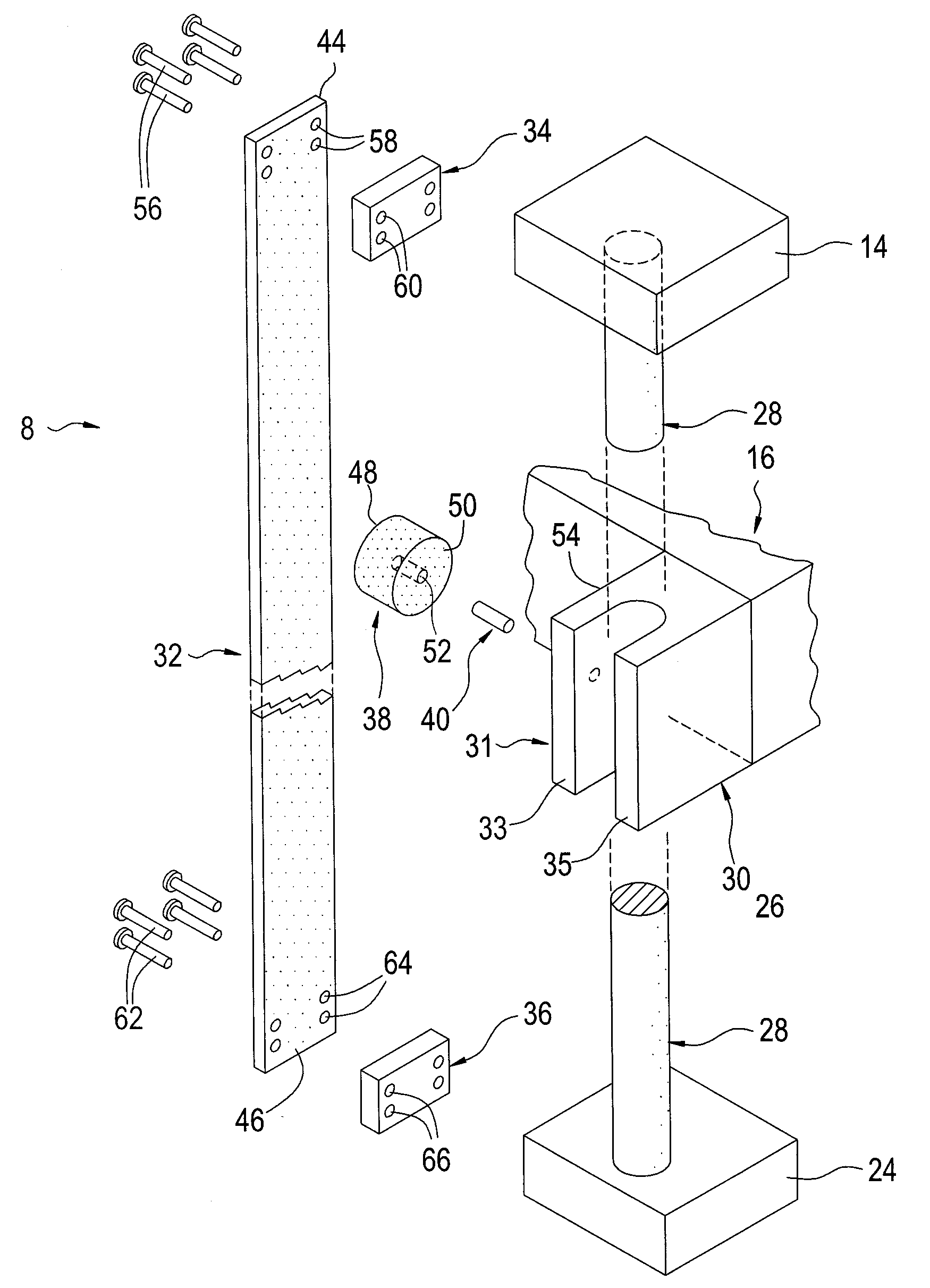
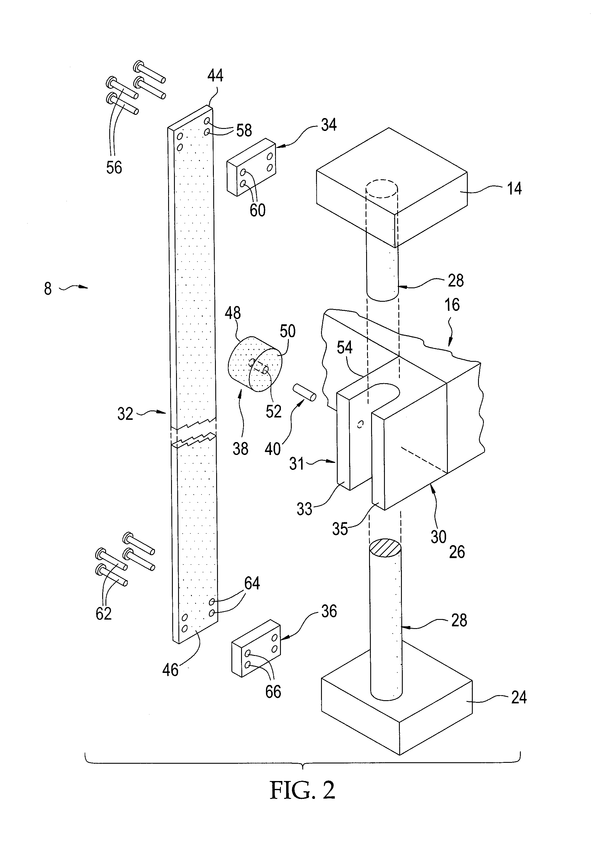
[0020]Stabilizer kit 8 was fitted to each of the four guide assemblies of Tiger Machine Co., Ltd.'s Model PG6 Block Machine after the lateral and front to back movement of the compression head of the machine was observed and measured as the compression head was actuated downward by a pair of hydraulic cylinders. The tolerance between the mold plunger and the mold box of the machine was also measured. It was recorded that the undesired movement of the head as it was actuated downward was ¼ of an inch at the point where the mold plunger began to first engage the mold box. The tolerance between the mold plunger and mold box was observed to be 1 / 16 of an inch. After stabilizer kit 8 was fitted to each of the four guide assemblies of the machine as described above, the undesired movement of the compression was again measured at the point where the mold plunger first began to engage the mold box. It was observed that the undesired movement of the compression had been decreased to 1 / 16 of ...


PUM

PropertyMeasurementUnit
thickaaaaaaaaaa
lengthaaaaaaaaaa
diameteraaaaaaaaaa

Abstract

A stabilizer kit for a compression head of a concrete block machine is provided, the kit including a stabilizer plate, a fiber disc, a stud, a pair of spacer plates and a set of bolts for attaching the stabilizer plate and a pair of spacer plates to and between an upper portion and a lower portion of a frame of the block machine.

Description

FIELD OF THE INVENTION [0001]This invention relates in general to an apparatus for molding concrete-blocks. More particularly, this invention relates to a compression head stabilizing device for stabilizing a compression head of a concrete block machine.BACKGROUND OF THE INVENTION [0002]Concrete block machines are used to fabricate concrete blocks, including for example, cinder blocks and keystone pavers. As depicted in FIG. 1, block machines typically include a compression head 16, a mold plunger 18 extending downward from a bottom side of the compression head and a mold box 22 situated below and alignable with the mold plunger. In use, concrete, which typically includes a damp mixture of cement, sand and aggregate, is deposited into the mold box 22 and the compression head pivoted downward bringing the plunger head 18 into engagement with the mold box for compressing the concrete into a style of blocks dictated by the corresponding arrangement of the plunger head and the mold box....

Claims


Application Information

Patent Timeline
Patent Type & Authority Patents(United States)
IPC IPC(8): B28B3/04
CPCB28B3/02B28B3/028B30B15/041Y10T29/49947Y10T29/49826
Inventor WOMACK, JOHNNY
Owner WOMACK JOHNNY
Why Eureka
Try Eureka