Safety valve for the venting circuit of a liquid tank

a safety valve and liquid tank technology, applied in the direction of valves, functional valve types, valve operating means/releasing devices, etc., can solve the problems of liquid entanglement, overpressure that has to be relieved, pressure rise inside the tank, etc., to prevent the seal from leaking, limit the risk, and minimize the effect of lateral movemen

Inactive Publication Date: 2012-09-18
PLASTIC OMNIUM ADVANCED INNOVATION & RES SA
View PDF28 Cites 6 Cited by
  • Summary
  • Abstract
  • Description
  • Claims
  • Application Information

AI Technical Summary

Benefits of technology

[0039]In this embodiment, there are preferably at least three fingers so as to prevent the seal from leaking between two consecutive fingers. Most particularly preferably, there are at least four of them so as to limit this risk. These fingers are preferably placed symmetrically on the head of the float, and therefore in the form of a cross with equal branches when there are four of them. Most particularly preferably, these fingers guide the seal during its vertical travel, so as to minimize its lateral movements.
[0040]Advantageously, the shape of the head of the float, and in particular the portion on which the seal rests in certain positions of the valve, is convex (domed or conical) so as to prevent the seal from sticking on the head in the event of liquid being deposited at this point.

Problems solved by technology

The disadvantage of such valves is that when the aperture is closed off for a long time (for example when the tank remains for a long period at its maximum fill level), the pressure rises inside the tank and can no longer be relieved by said aperture, hence the occurrence of an overpressure that has to be relieved by an additional device.
The drawback of such a valve is therefore that, if a wave occurs when the diaphragm and the needle are decoupled (that is to say during relief of an overpressure), liquid can be entrained into the system, (since the float is blocked and cannot move in order to close off the aperture).
Furthermore, in this very situation and / or in the event of a large overpressure, there is a risk of the central part of the diaphragm remaining stuck against the upper wall of the valve, and thus blocking the venting aperture.

Method used


Image

  • Safety valve for the venting circuit of a liquid tank
  • Safety valve for the venting circuit of a liquid tank

Examples


Embodiment Construction

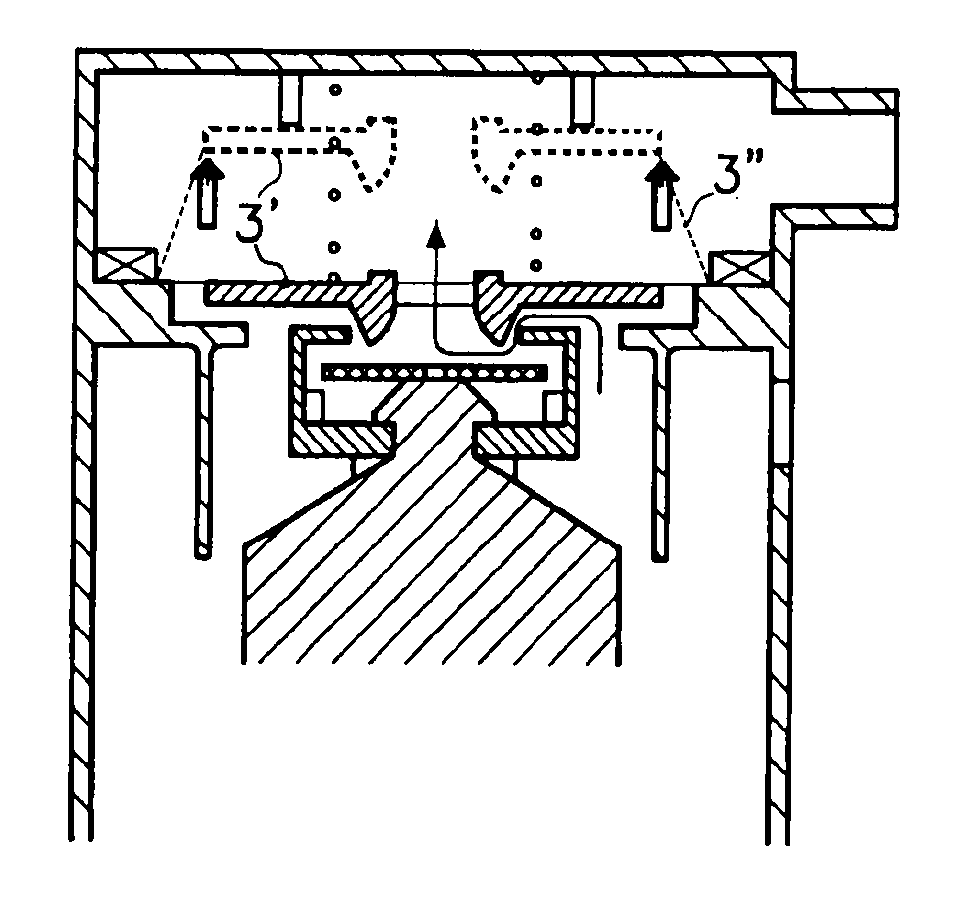
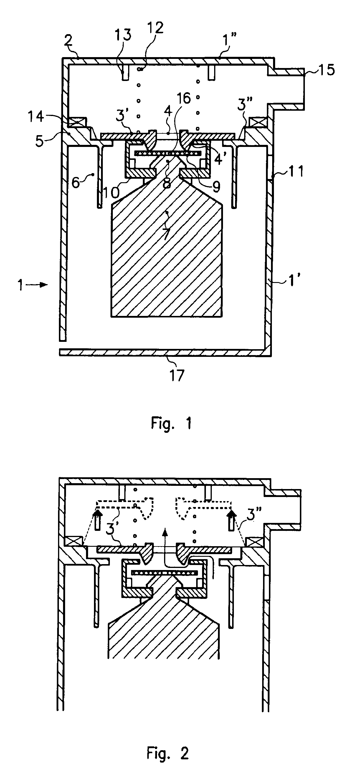
[0051]The safety valve illustrated in these figures comprises a chamber (1) that extends inside the tank (not shown) and is provided with a cover (2) and with an impermeable base (17). This chamber (1) also includes a moveable wall (3) having a rigid central portion (3′) provided with a venting aperture (4), and a flexible peripheral portion (3″) consisting of a diaphragm. The edge of the aperture (4) is provided with a lip (4′) having a geometry that promotes effective sealing. This wall (3) rests on a circular groove (5) moulded as one part with a cylindrical baffle (6) in which the head of a float (7) slides. This float (7) includes a needle (8) (produced as a single part with the float) on which a seal (9) having an aperture (16) rests and which is surrounded by fingers (10) that limit its vertical travel relative to the needle. The chamber (1) includes, in its lower portion (1′), a lateral opening (11) that allows the flow of gases. It also includes, in its upper portion (1″), ...


PUM


Abstract

Safety valve for the venting circuit of a liquid tank Safety valve for the venting circuit of a liquid tank, comprising: a) a chamber (1) provided with a cover (2), which extends at least partly into the tank and is connected via an aperture (4) to the venting circuit; b) a float (7), which can slide vertically inside the chamber (1) and close off the venting aperture (4) in a high position; and c) a moveable wall (3), which divides the chamber (1) into a lower portion (1′) in which the float (7) slides and an upper portion (1″) which connects with the venting circuit, this wall (3) being a moveable wall and having the venting aperture (4), said valve further including an aperture stop (13) integral either with the moveable wall (3) or with the cover (2).

Description

BACKGROUND OF THE INVETNION[0001]1. Field of the Invention[0002]The present invention relates to a safety valve for the venting circuit of a liquid tank, in particular a fuel tank with which a motor vehicle may be equipped.[0003]Liquid tanks, in particular fuel tanks for motor vehicles, are nowadays generally provided inter alia with a venting circuit. This circuit allows air to be introduced into the tank in the event of underpressure (especially for compensating for the volume of liquid consumed) or allows the gases contained in the tank to be removed in the event of overpressure (especially in the event of overheating). This circuit also allows the ducting and possible filtering of the gases that have to be discharged into the atmosphere, for the purpose of meeting the ever stricter environmental requirements in this regard.[0004]2. Description of the Prior Art[0005]The venting circuit generally includes a safety valve of the ROV (roll-over valve) type which as far as possible pr...

Claims


Application Information

Patent Timeline
Patent Type & Authority Patents(United States)
IPC IPC(8): F16K24/04
CPCF16K17/36F16K24/042B60K15/03519Y10T137/0874Y10T137/3099Y10T137/7423
Inventor ARNALSTEEN, MICHEL
Owner PLASTIC OMNIUM ADVANCED INNOVATION & RES SA
Why Eureka
Try Eureka