Semiconductor device

A technology of semiconductors and internal wires, applied in semiconductor devices, semiconductor/solid-state device components, electric solid-state devices, etc., can solve problems such as difficult injection of resin and obstruction of resin flow

Inactive Publication Date: 2009-04-01
RENESAS ELECTRONICS CORP
View PDF2 Cites 0 Cited by
  • Summary
  • Abstract
  • Description
  • Claims
  • Application Information

AI Technical Summary

Problems solved by technology

In addition, during resin sealing, since the lead hinders the flow of resin

Method used


Image

  • Semiconductor device
  • Semiconductor device
  • Semiconductor device

Examples


Embodiment approach 1

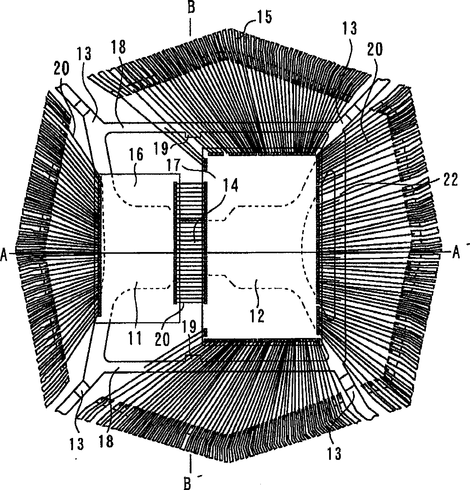
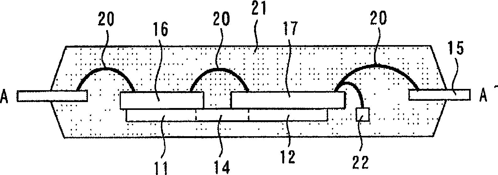
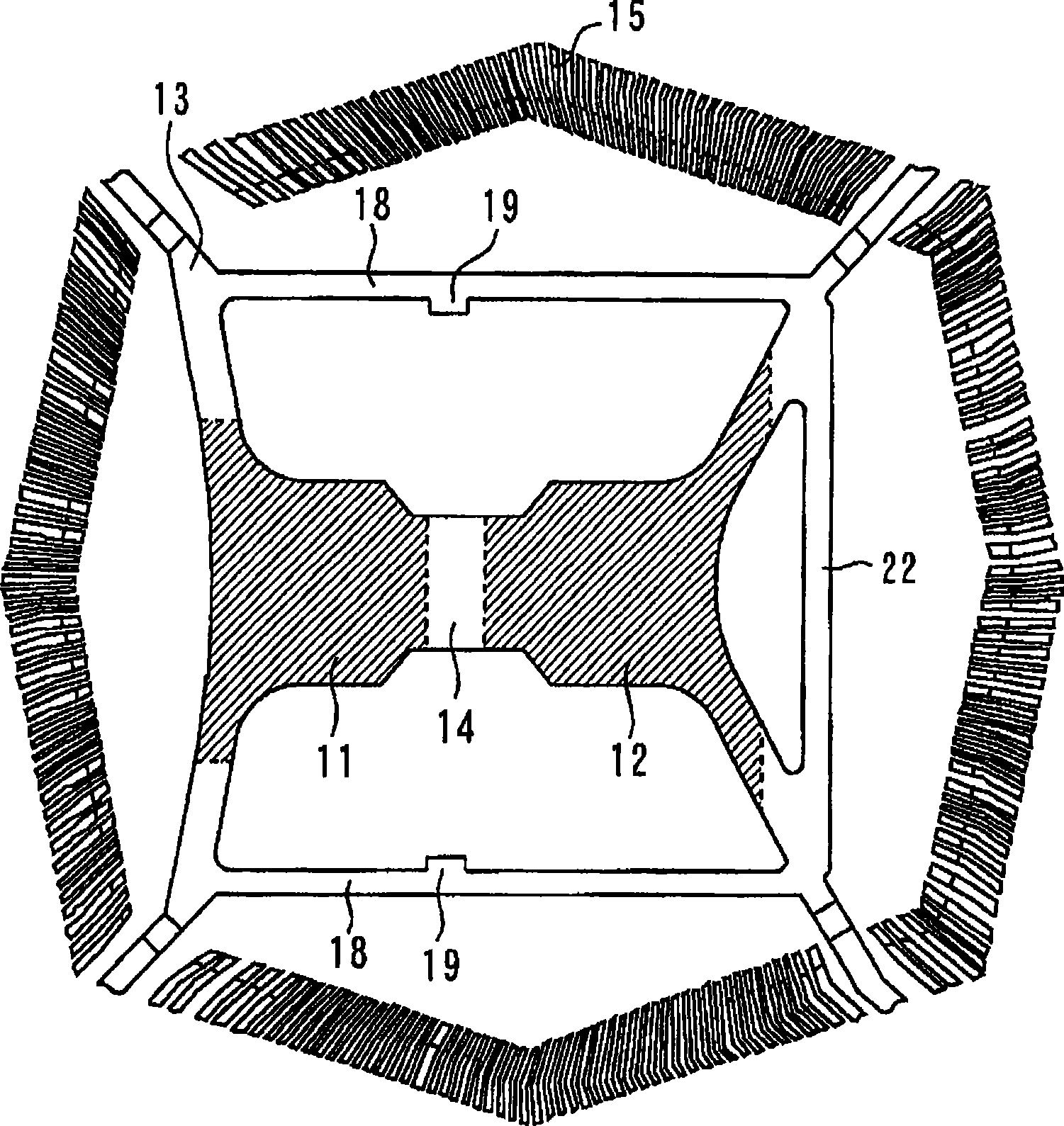
[0027] figure 1 is a plan view showing the inside of a semiconductor device according to an embodiment of the present invention, figure 2 yes figure 1 Cross-sectional view of A-A′. Figure 10 yes figure 1 Cross-sectional view of B-B′. The first lower backing plate 11 (first portion) and the second lower backing plate 12 (second portion) are arranged side by side. The first and second lower backing plates 11 , 12 are supported by suspension wires 13 , and both are connected by connecting wires 14 . The first and second lower backing plates 11, 12, the connection lead 14, and the suspension lead 13 constitute a metal mounting member in which metal parts are integrally molded. A plurality of inner leads 15 are arranged around the first and second lower backing plates 11 and 12 .

[0028] The first chip 16 has its principal surface overlapped with the first lower substrate 11 and is mounted on the principal surface of the first lower substrate 11 with paste (not shown). ...

Embodiment approach 2

[0052] In this Embodiment 2, if Figure 7As shown, instead of providing markings on the horizontal bars 18 as in the first embodiment, recesses 24 are provided as markings on the connection leads 14 . That is, the mounting member has a connection wire 14 (third portion) that is located between the first and second chips 16, 17 and that connects the first underlayment 11 (first portion) and the second underlayment 12 (second portion). . Further, on the side surface continuous from the first lower backing plate 11 to the second lower backing plate 12 via the connecting wire 14 , a concave portion 24 dented toward the inner side of the side surface is provided. The bottom part of the recess 24 lies at least on the connecting wire 14 . and, if Figure 8 As shown, the first and second chips 16 , 17 are mounted on the lower pads 11 , 12 . Other structures are the same as those in Embodiment 1. In this way, when the chips 16 and 17 are mounted on the lower substrate, the first a...


PUM


Abstract

This invention refers to a semiconductor device capable of easily performing chip contraposition when a lower die pad carries two chips in transversely arranged. A plurality of inner leads (15) is arranged around the first and second die pads which are arranged side by side. First and second chips (16, 17) are mounted on the first and second die pads (11, 12). A bar (18) is provided between the first and second chips (16, 17) and the plurality of inner leads (15), extending in an array direction of the first chip (16) and the second chip (17). A plurality of wires connects the first and second chips (16, 17) and the plurality of inner leads (15) and connects the first chip (16) and the second chip (17); and a resin (21) seals the first and second die pads, the plurality of inner leads, the first and second chips, the plurality of wires and the bar, wherein the bar (18) comprises a bump (19) as a mark provided at a position corresponding to an area between the first chip (16) and the second chip (17) in an array direction of the first chip and the second chip.

Description

technical field [0001] The present invention relates to a so-called SIP (System In Package) type semiconductor device in which two chips are mounted side by side on a sub-substrate and sealed with a resin. Background technique [0002] Figure 9 It is a plan view showing a conventional semiconductor device in which two chips are mounted laterally on a large submount. Two chips 16 and 17 are mounted on the lower backing plate 31 . Here, the lower backing plate 31 is larger than the chips 16 , 17 . Chips 16 , 17 are connected to a plurality of internal wires 15 by a plurality of leads 20 , and chips 16 , 17 are connected to each other. Between the chips 16 , 17 , a slit 32 is formed on the lower backing plate 31 . In the manufacturing process of the semiconductor device, when the chips 16 and 17 are mounted on the sub-substrate 31 , the ends of the sub-substrate 31 and the slits 32 are marked and aligned. Also, Patent Document 2 describes a semiconductor device in which on...

Claims


Application Information

Patent Timeline
IPC IPC(8): H01L25/00H01L25/065H01L23/488H01L23/495H01L23/544H01L23/31
CPCH01L2224/48137H01L2224/73265H01L2224/32245H01L2224/48247H01L2924/181H01L24/73H01L2224/05554H01L2224/48091H01L2924/00012H01L2924/00014H01L23/48
Inventor 三角和幸畑内和士
Owner RENESAS ELECTRONICS CORP
Why Eureka
Try Eureka