Apparatus for affixing a dock to an inboard mooring pole

a technology for attaching a dock and an inboard mooring pole, which is applied in the field of enhanced utilization of mooring poles, can solve the problems of affecting the service life of the dock, the mooring of floating docks (and the attachments thereto such as “fingers”) to the pilings, and the wear and damage of both docks and piles, so as to achieve sufficient buoyancy, enhance the buoyancy of the floating dock, and the effect of great buoyancy

Active Publication Date: 2009-04-09
LEMONIDES DIMITRI
View PDF9 Cites 3 Cited by
  • Summary
  • Abstract
  • Description
  • Claims
  • Application Information

AI Technical Summary

Benefits of technology

[0048]The outer surface of the buoyant base is advantageously covered by a tough, resilient cover, such as, for example, a polyvinyl, polyester or nylon composition. The cover may be fabricated of one or more sections and tied (or otherwise affixed) to the outer surface of the buoyant base. The inner core of the buoyant base is comprised of example, a circumferential polyethylene, polyvinyl or polyester hollow tube positioned within the core. Additionally, the core of the buoyant base is filled with a buoyant material such as, for example, a polystyrene foam thereby imparting great buoyancy to the base. In preferred embodiments of the present invention utilizing a buoyant base, the buoyant material utilized within the base demonstrates sufficient buoyancy so as to assure that the entire length of the cylindrical sleeve distal (superior) to the distal (superior) terminus of the base lies above the water line when the apparatus is applied to a pile.
[0049]In embodiments of the present invention including a buoyant base, it is preferred—but not required—that the buoyant base be located from about 2 to about 5 feet from the inferior terminus of the sleeve. This configuration allows the buoyant base to aid in enhancing the buoyancy of the floating dock to which the cylindrical sleeve is affixed while, simultaneously serving as an additional shock absorber.
[0050]As mentioned above, the apparatus of the present invention is especially configured for floating docks wherein the height of the dock, relative to adjacent pilings, is subject to change in accordance with changing tides, water levels, etc. and in circumstances wherein wave an other water movements tend to cause a floating dock to list. As also mentioned above, the present invention also provides, with embodiments incorporating a buoyant base mounted upon the cylindrical sleeve, a means of increasing dock buoyancy to a floating dock as well as provid

Problems solved by technology

It is well known that the mooring floating docks (and attachments thereto such as “fingers”) to pilings is often complicated by changing tides.
In some areas, such changes in tides—from low tide to high tide—may be so great as to cause great stress, friction and wear to both floating docks and the mooring poles which hold such docks in place.
As tide levels cycle throughout the day, both dock and pile are subjected to wear and damage caused by the movement of each relative to the other.
In addition, waves, wake and other water disturbances may cause additional damage to both pilings and docks by virtue of the impacts suffered therebetween.
In addition, a floating dock secured to a mooring post may become dangerously tilted, damaged and/or capsized during tide changes if the means of securing the dock to the pile(s) does not allow for vertical movement along the pile(s) during such tide changes.
However, the incessant changes in tide coupled with the action of waves and wakes, over time, will almost certainly cause the loss of such protective devices.
Although such moldings and bumpers may be replaced, constant vigilance and maintenance is required due to the inherent deficiencies of such devices.
With time, portions of such foam may break away, become saturated with water, or otherwise loose the buo

Method used


Image

  • Apparatus for affixing a dock to an inboard mooring pole
  • Apparatus for affixing a dock to an inboard mooring pole
  • Apparatus for affixing a dock to an inboard mooring pole

Examples


Embodiment Construction

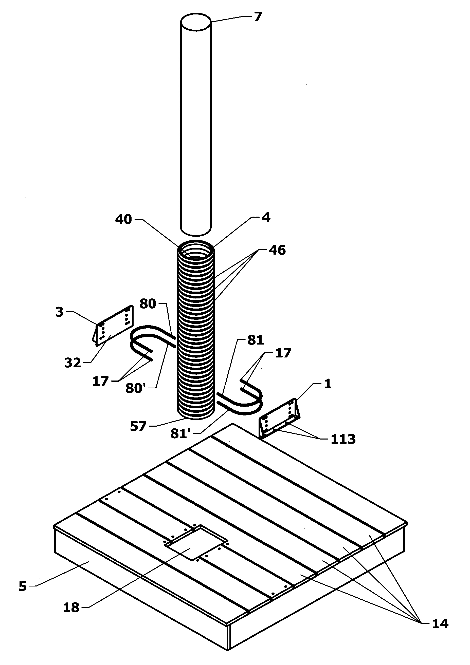
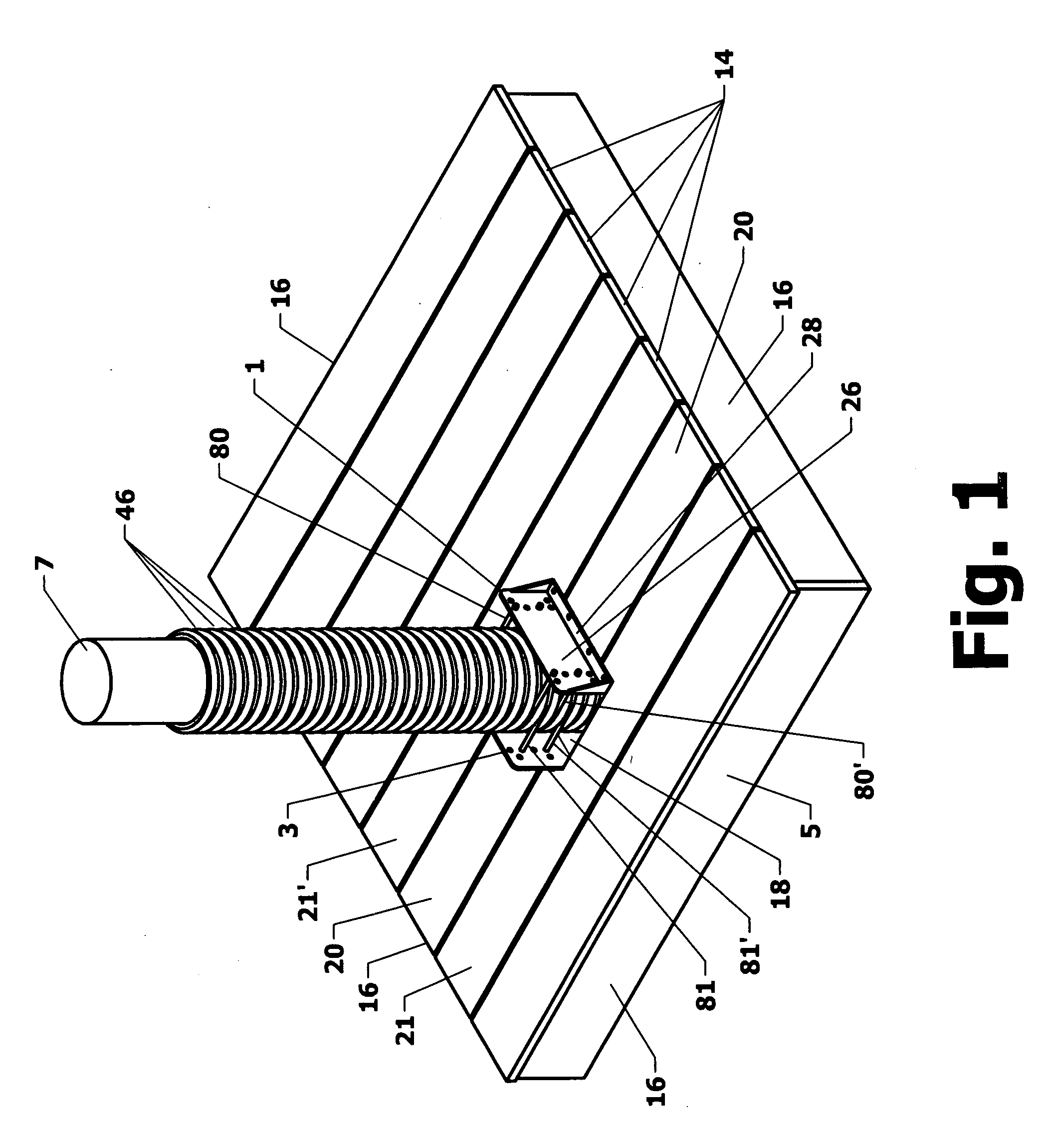
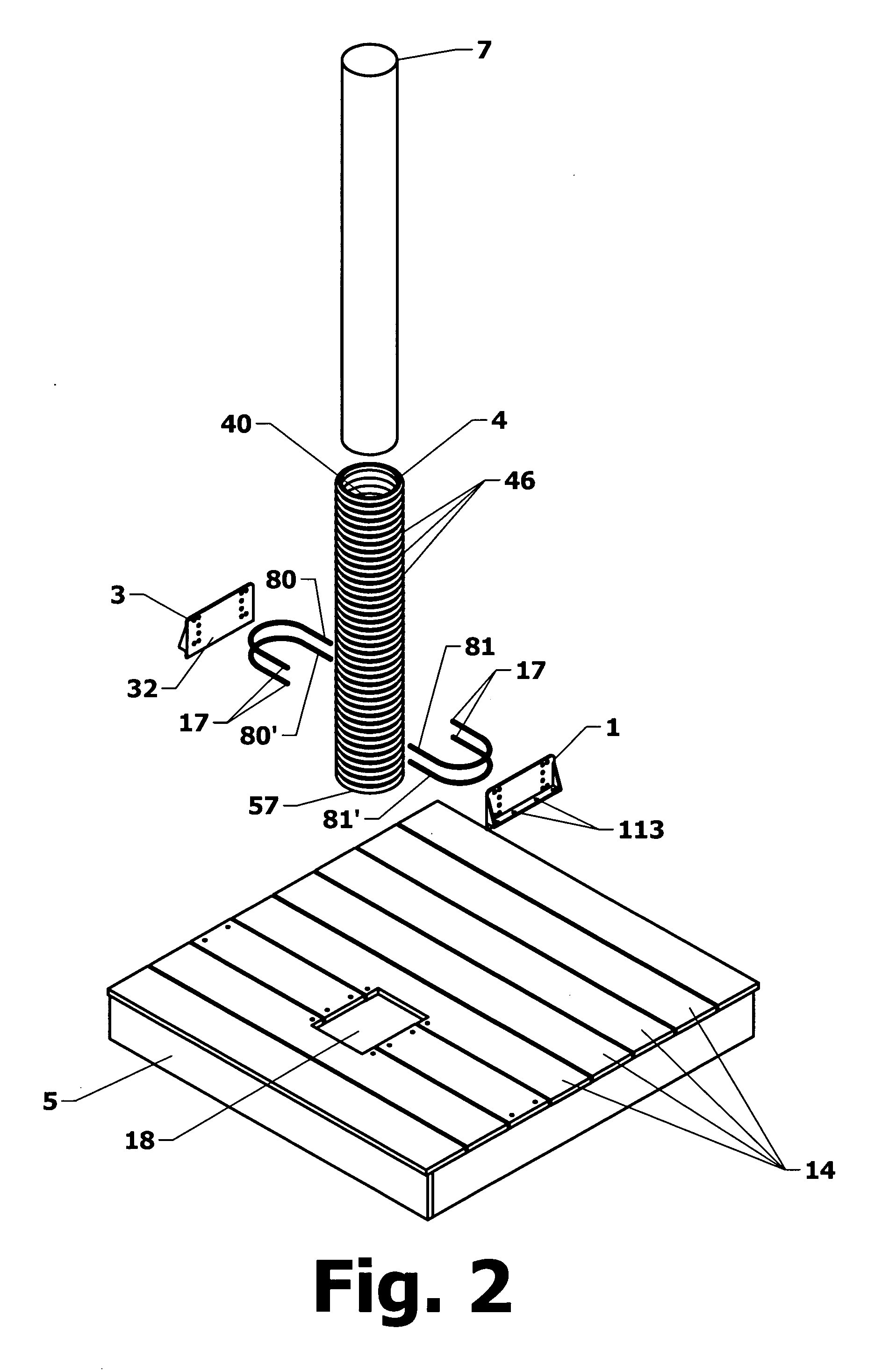
[0061]FIG. 1 illustrates a preferred embodiment of the present invention wherein two brackets comprised of “L” shaped base plates 1 and 3 and “U” shaped arms depending therefrom are utilized to moore floating dock 5 to pile 7. More specifically, cylindrical sleeve 4 is coaxially mounted upon pile 7. The central bore of the cylindrical sleeve is selected to demonstrate a dimension, as discussed above, so as to enable the sleeve to slip over and, thereafter, move up and down along a length of the pile without binding so as to accommodate motion of the dock caused by changes in tide, currents, wave activities and other disturbances. As discussed above, each of the brackets includes one or more “U” shaped arms (80, 80′, 81, &81′) which, as described in more detail, above and below, engage selected circumferential grooves 46 of the outside surface of the cylindrical sleeve, so as to anchor the sleeve, and the pile therewithin, to the floating dock each bracket is affixed to.

[0062]Dock 5 ...


PUM


Abstract

An apparatus is disclosed especially configured and adapted for mooring a floating dock to an inboard mooring pile—a pile positioned within and extending through the top deck of a floating dock—. The apparatus minimizes damage to both dock and mooring piles caused by changes in tide, waves, wake and other water disturbances while, simultaneously, adding stability to the floating dock—especially in regarding to listing—. The apparatus is comprised of a cylindrical sleeve which is coaxially applied to a mooring pile, a dock mounted mooring bracket comprised of a base plate which connects to the sleeve mounted upon the pile via at least one “U” shaped arm. The arm, in turn, extends, and is mounted upon a vertical planar portion of the base plate and is disposed in a parallel relation to the top surface of the floating dock. An inner, semi-circular portion of the “U” shaped arm engages selected and parallel circumferential grooves formed in the outer surface of the sleeve. The base plate, in turn, is affixed to a structurally sound portion of the floating dock adjacent to a pile aperture through which the mooring pile extends. In certain alternate preferred embodiments, an elongated rod is utilized to firmly engage a selected circumferential groove of the columnar sleeve. In such embodiments, the elongated rod is mounted to the floating via a mounting means at both termini of the elongated rod. Embodiments utilizing elongated rods for engagement of the columnar sleeve utilize at least two such rods and engage the columnar sleeve on opposite sides thereof.

Description

[0001]This application is a continuation-in-part of U.S. patent application Ser. No. 11 / 699,181 filed Jan. 29, 2007 which, in turn, is a continuation-in-part of U.S. patent application Ser. No. 11 / 026,791 filed Dec. 31, 2004, the entire specification of each said applications is hereby incorporated herein by reference.TECHNICAL FIELD[0002]The device and method disclosed herein relate generally to marine mooring systems. More specifically, the disclosed device and method of use thereof relates to enhanced utilization of mooring poles for securing floating docks.BACKGROUND OF THE ART[0003]It is well known that the mooring floating docks (and attachments thereto such as “fingers”) to pilings is often complicated by changing tides. In some areas, such changes in tides—from low tide to high tide—may be so great as to cause great stress, friction and wear to both floating docks and the mooring poles which hold such docks in place. For example, a dock may be moored to one or more mooring p...

Claims


Application Information

Patent Timeline
IPC IPC(8): B63B21/00
CPCB63B21/00E02B3/064B63B21/04
Inventor LEMONIDES, DIMITRI
Owner LEMONIDES DIMITRI
Why Eureka
Try Eureka