Rotary compressor with permanent magnet motor

Inactive Publication Date: 2006-11-02
TECUMSEH PROD CO
View PDF54 Cites 0 Cited by
  • Summary
  • Abstract
  • Description
  • Claims
  • Application Information

AI Technical Summary

Benefits of technology

[0009] The present invention includes a rotary compressor comprising a rotor having permanent magnets and a stator where the rotor is aligned with respect to the stator via a magnetic attraction between the permanent magnets and the stator. In one embodiment, the compressor includes a housing which is configured such that the rotor does not entirely bear against a top or bottom portion of the compressor housing. In this embodiment, the permanent magnets of the rotor are sized and configured such that the magnetic attraction between the rotor magnets and the stator, regardless of whether the stator is energized, positions, or suspends, the rotor substantially intermediate the top and bottom portions of the housing. As a result, less or, possibly, even no friction is

Problems solved by technology

Electronic components, such as microprocessors and other integrated circuits, for example, typically generate a lot of heat during operation.
Previous refrigerant-based cooling systems were typically very large and heavy and often required more power to operate than the entire electronic system that they were cooling.
As a result, a complex system of tubing or plumbing was necessary to bring the cooling refrigerant into thermal exchange with the electronic components.
Consequently, these refrigerant-based cooling systems were not modular and self-contained and often required special expertise and tools for their operation and maintenance.
In addition, previous refrigerant-based cooling systems were not directly attached to the components that needed to be cooled and a dedicated cooling unit was typically not p

Method used


Image

  • Rotary compressor with permanent magnet motor
  • Rotary compressor with permanent magnet motor
  • Rotary compressor with permanent magnet motor

Examples


Example

[0016] Corresponding reference characters indicate corresponding parts throughout the several views. Although the exemplifications set out herein illustrate an embodiment of the invention, the embodiment disclosed below is not intended to be exhaustive or to be construed as limiting the scope of the invention to the precise form disclosed.

DETAILED DESCRIPTION

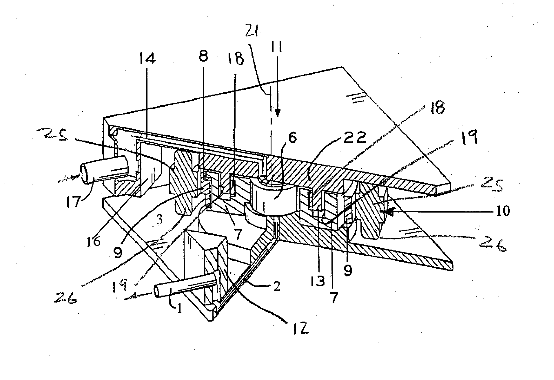
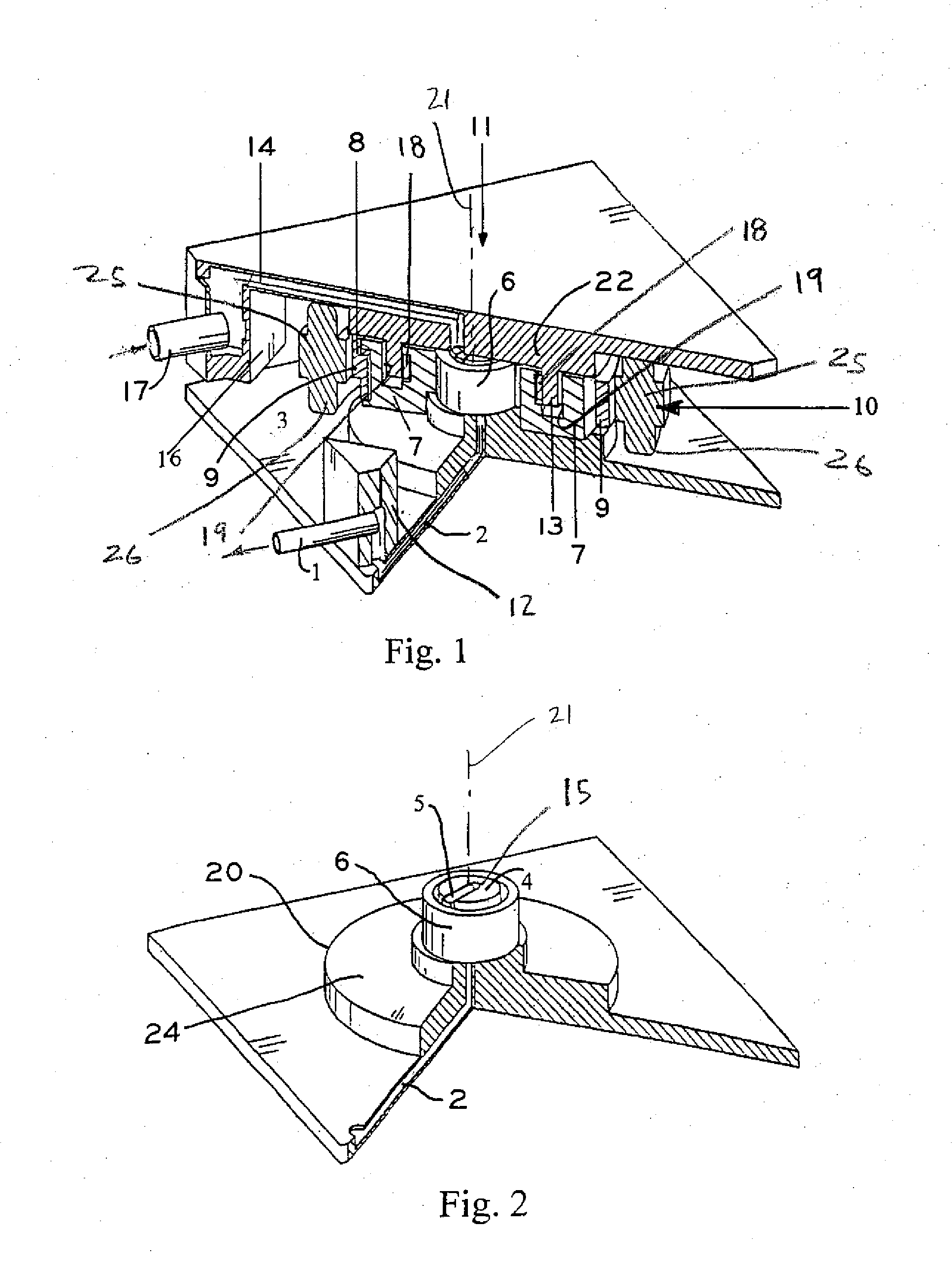
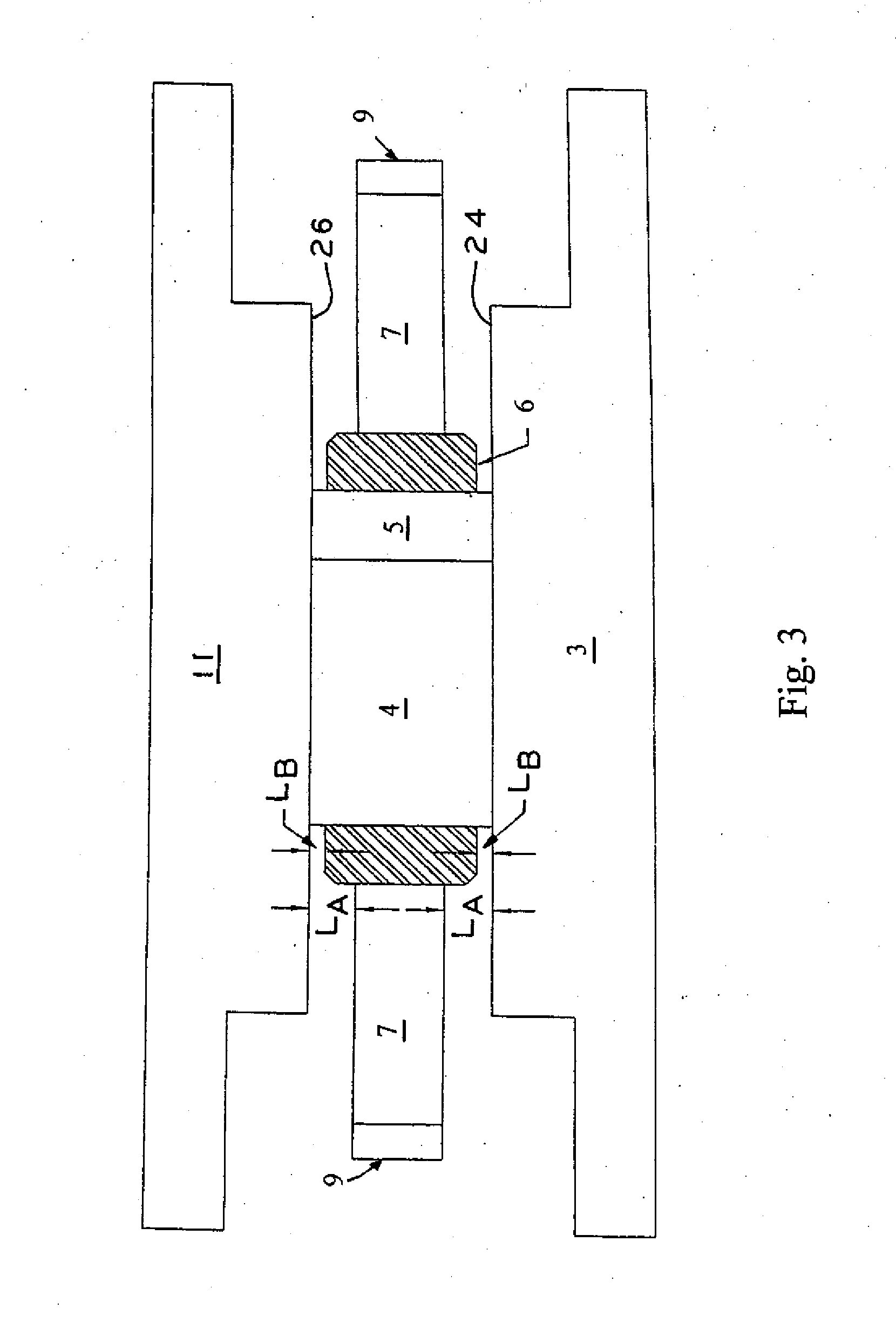
[0017] Refrigeration circuits typically comprise, in serial order, a compressor, a condenser, a throttling valve, and an evaporator. Referring to the exemplary rotary compressor illustrated in FIG. 1, refrigerant, such as R245fa, for example, enters the rotary compressor through suction inlet 17. The refrigerant then flows through distributor 16, and passage 14 in top plate 11 where it is drawn into a chamber defined between post 4, vane 5 and roller 6 of a compression, or pump, mechanism. As described in further detail below, roller 6 is positioned eccentric with respect to post 4 such that, when roller 6 is orbited with resp...


PUM


Abstract

A rotary compressor comprising a rotor having a plurality of permanent magnets mounted thereon and a stator, where the rotor is aligned with respect to the stator via a magnetic attraction between the permanent magnets and the stator. The compressor includes a housing and is configured such that the rotor does not entirely bear against a top or bottom portion of the compressor housing. The permanent magnets of the rotor are sized and configured such that the magnetic attraction between the magnets and the stator, regardless of whether the stator is energized, positions, or suspends, the rotor substantially intermediate the top and bottom portions of the housing. As a result, less or, possibly, even no friction is experienced between the rotor and the compressor housing which reduces the potential for the rotor to seize or stall and allows the compressor to be operated with little or no oil.

Description

CROSS REFERENCE TO RELATED APPLICATION [0001] This application claims the benefit under 35 U.S.C. §119(e) of U.S. Provisional Patent Application Ser. No. 60 / 675,623, entitled ROTARY COMPRESSOR WITH PERMANENT MAGNET MOTOR, filed on Apr. 28, 2005, the entire disclosure of which is hereby expressly incorporated by reference herein.BACKGROUND OF THE INVENTION [0002] 1. Field of the Invention[0003] The present invention relates to rotary compressors. More specifically, the present invention relates to rotary compressors including a rotor and a stator where the rotor includes permanent magnets which align the rotor with respect to the stator. [0004] 2. Description of the Related Art [0005] Electronic components, such as microprocessors and other integrated circuits, for example, typically generate a lot of heat during operation. Dissipating this heat has become increasingly important to improve the working life and efficiency of these components. In the past, air based cooling systems wer...

Claims


Application Information

Patent Timeline
IPC IPC(8): F04B17/00
CPCF01C21/0845F04C29/0085F04C18/3441F01C21/0863
Inventor MANOLE, DAN M.MOORE, MICHAEL J.
Owner TECUMSEH PROD CO
Why Eureka
Try Eureka