Metered dose valve

Active Publication Date: 2011-02-24
KINDEVA DRUG DELIVERY LP
View PDF18 Cites 5 Cited by
  • Summary
  • Abstract
  • Description
  • Claims
  • Application Information

AI Technical Summary

Benefits of technology

[0030]Also for enhanced single positional stability and/or further reduction of any potential for bimodal behavior, it is desirable to construct and arrange the valve such that the outer periphery of a major surface of the metering gasket is pulled radially outwards into tension.
[0031]At the rest position of the valve stem, the metering gasket may be biased inwardly (i.e. with the inner periphery of the metering gasket positioned away from the body portion of the valve stem) or outwardly (i.e. with the inner periphery of the metering gasket positioned towards the body portion of the valve stem). For enhanced positional stability and/or avoidance of a potential for bimodal behavior, preferably the metering gasket is biased inwardly. Such preferred valves where the metering gasket is biased inwardly are particularly advantageous when the valve is configured and arranged such that during routine operation of the valve the metering gasket will not move into a substantially planar position (and consequently will not move through such a substantially planar position into an outward position).
[0032]Valves in accordance with the present invention use a metering gasket, which forms a face seal during actuation and which is advantageously held in a stable deformed configuration when the valve stem is at rest, allowing for a return of the metering gasket to a consistent position when the valve stem returns to the rest position.
[0033]This is particularly advantageous for pMDI valves of the type described in WO.A-04/22142 in which the action of depressing the valve stem causes the formation of a transient metering chamber. Accordingly preferred embodiments of valves described herein are constructed and arranged as to allow the formation of a transient metering chamber upon depression of

Problems solved by technology

Because the point at which the metering gasket first seals off against the valve stem may define a metered volume of medicament formulation, such positional inconsistency has the potential to cause unwanted shot weight inconsistencies and hence poor control of dose metering.
Without wishing to be bound by any th

Method used


Image

  • Metered dose valve
  • Metered dose valve
  • Metered dose valve

Examples


Example

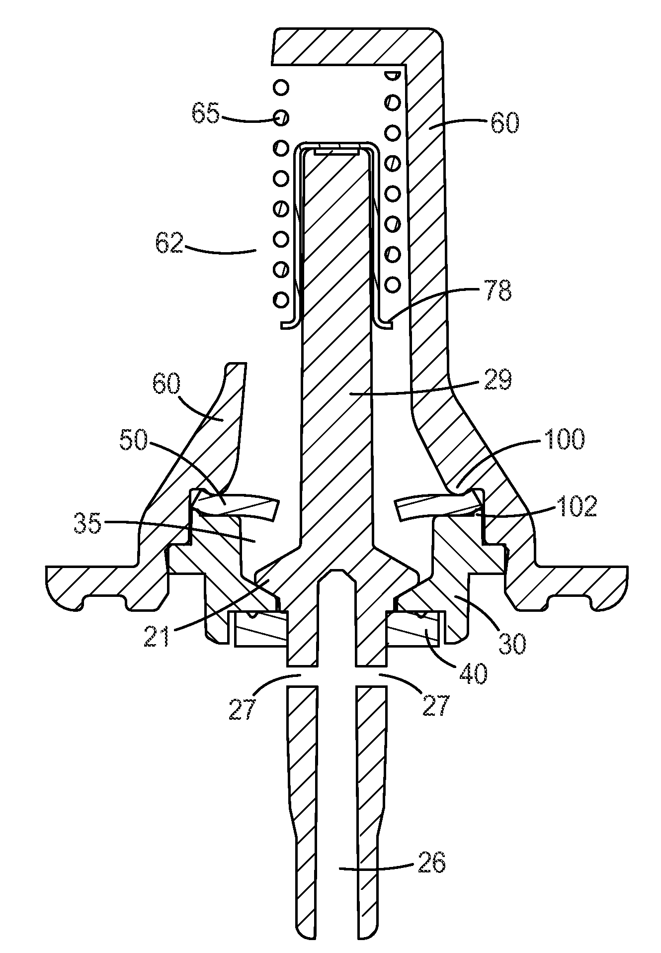
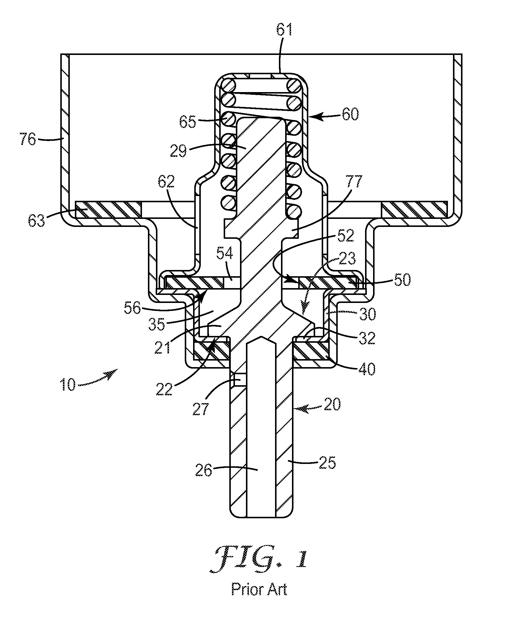
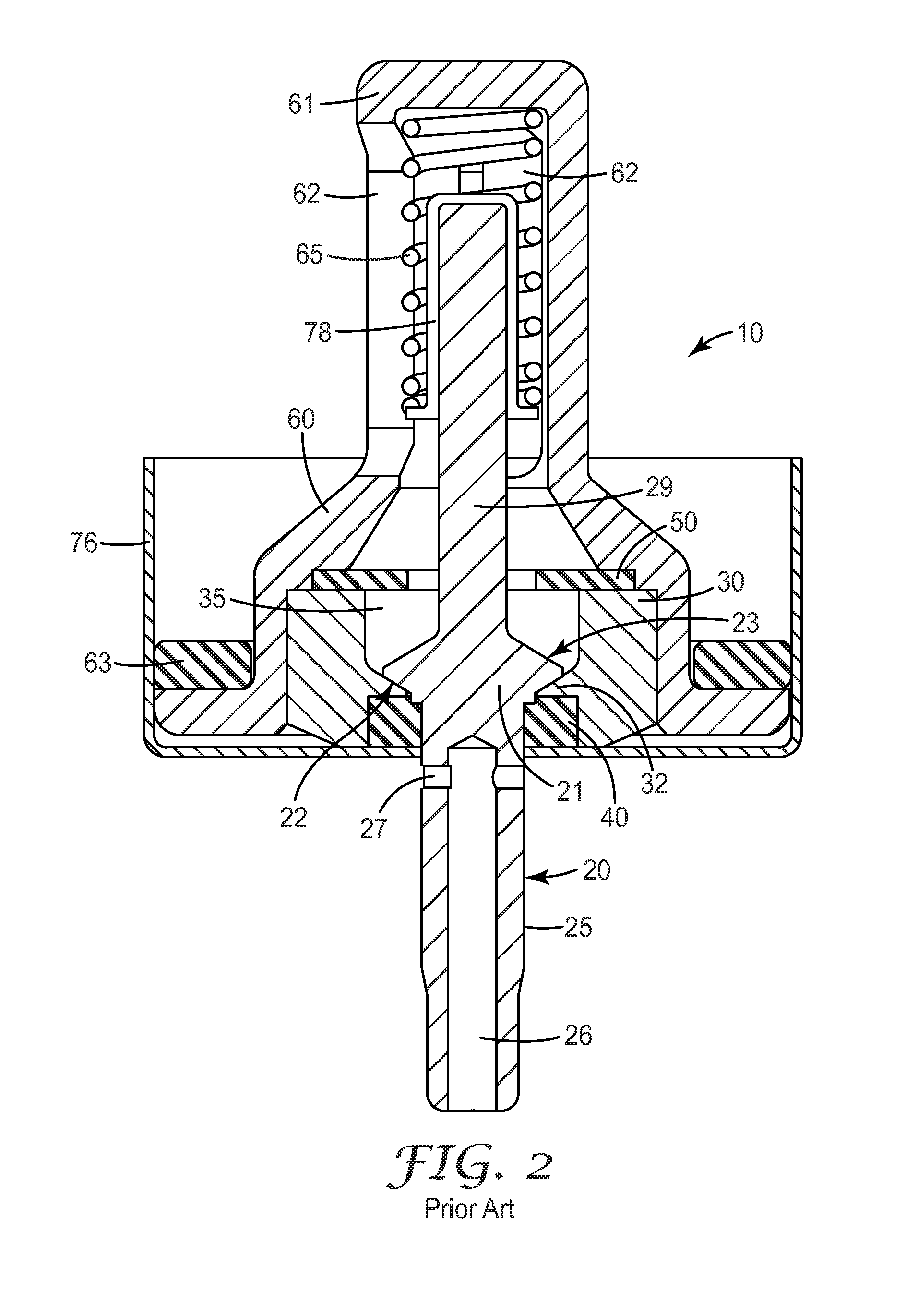
[0060]FIGS. 1 and 2 of the accompanying drawings illustrate aerosol valves of the type generally disclosed in WO 04 / 022142. The features of the valves in FIGS. 1 and 2 are similar and like reference numerals refer to like parts. The valve of FIG. 1 is designed for the valve stem, valve body and spring cage components to be constructed of metal, preferably stainless steel. The design of FIG. 2 allows these components to be made of plastics materials. FIGS. 3 to FIG. 23 illustrate exemplary aerosol valves in accordance with the present invention where again like reference numerals refer to like parts. For a better understanding of the present invention, in the following, common features of embodiments described herein will be first described, typically in reference to the embodiment shown in FIG. 4.

[0061]Referring to FIG. 4, aerosol valves (10) described herein typically comprise a valve ferrule (76) that allows the valve to be secured to an aerosol container (not shown) by crimping t...


PUM


Abstract

An aerosol metering valve comprising: (a) a valve stem movable between a rest position and a firing position comprising: a body portion comprising a circumferential sealing surface (b) a valve body comprising: a body wall, and an internal chamber defined at least in part by the body wall; and (c) a metering gasket having an inner periphery defining an aperture, being disposed near the most interior end of the internal chamber and being configured to be able to form a transient, substantially fluid-tight face seal against the circumferential sealing surface of the valve stem, where at the rest position of the valve stem, the body portion of the valve stem is located within the internal chamber and as the valve stem is moved from its rest position towards its firing position the circumferential sealing surface of the valve stem contacts the metering gasket to form a face seal thereby closing a metering chamber and thereafter further movement of the valve stem towards its firing position causes the metering gasket to deflect while maintaining the seal with the circumferential sealing surface of the valve stem; and wherein the metering gasket in an unbiased configuration is an annular disc having a substantially planar form and where the valve is constructed and arranged such that the inner periphery of the metering gasket is urged out of said substantially planar form at the rest position of the valve stem, or wherein the metering gasket is pre-biased into a dished-shape.

Description

FIELD[0001]The present invention relates to an aerosol metering valve, especially, although not exclusively, intended for use as a valve for a pressurized metered dose inhaler (pMDI).BACKGROUND[0002]One form of valve for a pMDI is described in WO-A-04 / 22142, which discloses an aerosol metering valve comprising:[0003](a) a valve stem that generally defines a longitudinal axis and comprises:[0004](1) a body portion comprising a proximal end, a distal end, and at least one side surface connecting the proximal end and the distal end and comprising a metering surface, wherein the longitudinal axis and a plane tangential to at least a portion of the metering surface define an angle from about 2° to about 90°, and[0005](2) a stem portion comprising a discharge passageway;[0006](b) a valve body comprising:[0007](1) a body wall that comprises a sealing portion,[0008](2) an internal chamber defined at least in part by the body wall and comprising a metering portion configured to substantially...

Claims


Application Information

Patent Timeline
IPC IPC(8): B65D83/00
CPCB65D83/54A61M15/009
Inventor HODSON, PETER D.GORING, MATTHEW A.HOWGILL, STEPHEN J.FIELDING, JOHNSHAW, RACHEL V.CHARNOCK, PAUL A.MCGLASSON, STUART A.HELM, STEPHEN D.JACKSON, GRAHAM V.BALKWILL, ANTHONY W.GRAVES, JASON A.
Owner KINDEVA DRUG DELIVERY LP
Why Eureka
Try Eureka