Mixer assembly for a gas turbine engine

Active Publication Date: 2015-05-07
RAYTHEON TECH CORP
View PDF0 Cites 4 Cited by
  • Summary
  • Abstract
  • Description
  • Claims
  • Application Information

AI Technical Summary

Benefits of technology

[0008]A mixer assembly for a gas turbine engine is provided, including a main mixer with fuel injection holes located between at least one radial swirler and at least one axial swirler, wherein the fuel injected into the main mixer is atomized and dispersed by the air flowing through the radial swirler and the axial swirler. This configura

Problems solved by technology

At the same time, the engine pressure ratio is getting higher and higher for increasing engine efficiency, lowering specific fuel consumption, and lowering carbon dioxide (CO2) emissions, resulting in significant challenges to designing combustors that still produce low emissions despite increased combustor inlet pressure, temperature, and fuel/air ratio.
However, one of the major challenges for the development of PLPP is the requirement to sufficiently premix the injected fuel and combustion air in the main mixer of a mixer assembly within a given mixing time, which is required to be significantly shorter than the auto-ignition delay time.
As a result, the degree of atomization and mixing may vary gr

Method used


Image

  • Mixer assembly for a gas turbine engine
  • Mixer assembly for a gas turbine engine
  • Mixer assembly for a gas turbine engine

Examples


Example

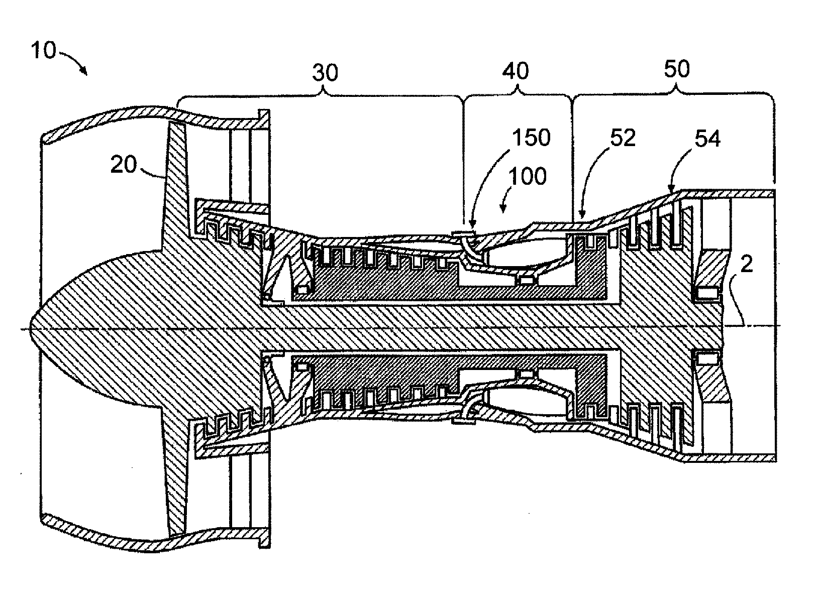
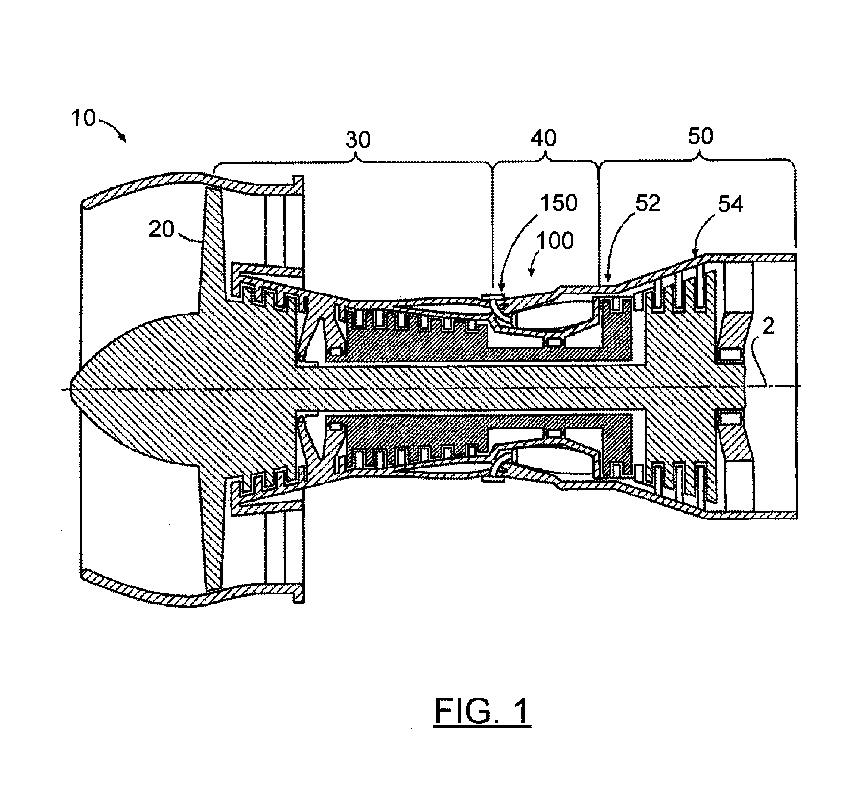
[0016]FIG. 1 is a schematic diagram of an exemplary embodiment of a gas turbine engine 10. The gas turbine engine 10 is depicted as a turbofan that incorporates a fan section 20, a compressor section 30, a combustion section 40, and a turbine section 50. The combustion section 40 incorporates a combustor 100 that includes a plurality of fuel injectors 150 that are positioned annularly about a centerline 2 of the engine 10 upstream of the turbines 52, 54. Throughout the application, the terms “forward” or “upstream” are used to refer to directions and positions located axially closer toward a fuel / air intake side of a combustion system than directions and positions referenced as “aft” or “downstream.” The fuel injectors 150 are inserted into and provide fuel to one or more combustion chambers for mixing and / or ignition. It is to be understood that the combustor 100 and fuel injector 150 as disclosed herein are not limited in application to the depicted embodiment of a gas turbine eng...


PUM


Abstract

A mixer assembly for a gas turbine engine is provided, including a main mixer with fuel injection holes located between at least one radial swirler and at least one axial swirler, wherein the fuel injected into the main mixer is atomized and dispersed by the air flowing through the radial swirler and the axial swirler.

Description

CROSS-REFERENCE TO RELATED APPLICATIONS[0001]This application is a continuation patent application under 35 USC §120 claiming priority to U.S. non-provisional patent application Ser. No. 13 / 014,388 filed on Jan. 26, 2011.STATEMENT OF FEDERALLY SPONSORED RESEARCH OR DEVELOPMENT[0002]This invention was made with Government support under Contract No. NNC08CA92C awarded by the National Aeronautics and Space Administration (NASA). The U.S. Government has certain rights in the invention.FIELD OF THE DISCLOSURE[0003]The subject matter disclosed herein relates generally to combustors for gas turbine engines and more particularly to mixer assemblies for gas turbine engines.BACKGROUND OF THE DISCLOSURE[0004]Gas turbine engines, such as those used to power modern aircraft, to power sea vessels, to generate electrical power, and in industrial applications, include a compressor for pressurizing a supply of air, a combustor for burning a hydrocarbon fuel in the presence of the pressurized air, an...

Claims


Application Information

Patent Timeline
IPC IPC(8): F23R3/28
CPCF23R3/286F23C7/004F23R3/14F23R2900/03343
Inventor DAI, ZHONGTAOCOHEN, JEFFREY M.FOTACHE, CATALIN G.SMITH, LANCE L.HAUTMAN, DONALD J.
Owner RAYTHEON TECH CORP
Why Eureka
Try Eureka