
Mobile communication terminal

a mobile communication terminal and terminal technology, applied in the direction of telephone set construction, antenna details, antennas, etc., can solve the problems of deterioration of wireless communication environment, thick mobile communication terminal, so as to improve the use environment and improve the efficiency of wireless communication

Inactive Publication Date: 2008-04-10
LG ELECTRONICS INC
View PDF13 Cites 8 Cited by
  • Summary
  • Abstract
  • Description
  • Claims
  • Application Information

AI Technical Summary

Benefits of technology

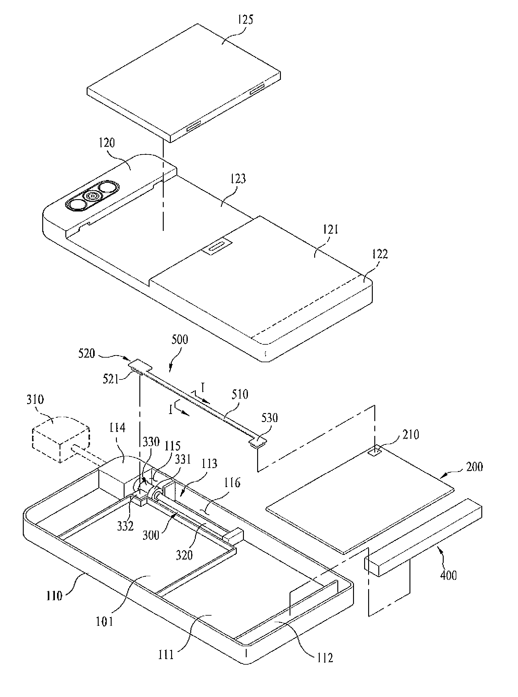
The present invention provides a mobile communication terminal that overcomes limitations and disadvantages of existing slim mobile communication terminals by improving wireless communication efficiency. The terminal includes an antenna unit with a separate feeding point from the PCB unit, allowing for better wireless communication. The antenna unit includes a head part, a body part, and a feeding part, with the feeding point connected to the PCB unit through a connector. The antenna unit can be positioned in the body using a holding member. The mobile communication terminal also includes a recess for battery mounting and a recess for the PCB unit, as well as a recess for the intenna unit. The FPCB unit includes a signal part and ground parts, and a bonding member or a bonding surface can be used to connect the feeding point with the PCB unit. The invention also provides a mobile communication terminal with a battery mounted on the rear of the body, a PCB unit on the lower portion of the body, an intenna unit on the side portion of the body, and an FPCB unit that connects the feeding point with the PCB unit.

Problems solved by technology

However, as a new structure is applied to a conventional mobile terminal, slimness of a conventional mobile terminal happens to face its limitation and it results in a thick mobile communication terminal.
In addition, the thick conventional mobile communication terminal might deteriorate wireless communication environments.

Method used


Image

  • Mobile communication terminal
  • Mobile communication terminal
  • Mobile communication terminal

Examples


Embodiment Construction

[0045] Reference will now be made in detail to the preferred embodiments of the present invention, examples of which are illustrated in the accompanying drawings.

[0046] A mobile communication terminal according to the present can be applicable to almost all kinds of mobile communication terminals including slide type, folder-type and swing-types mobile communication terminals.

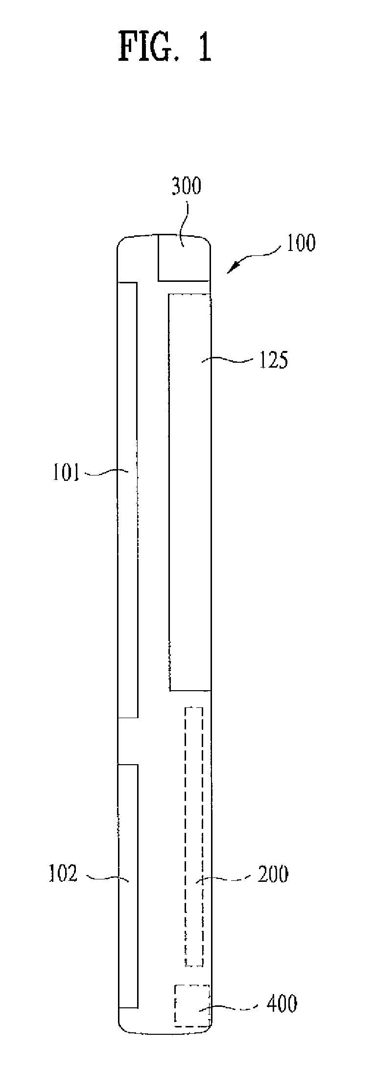
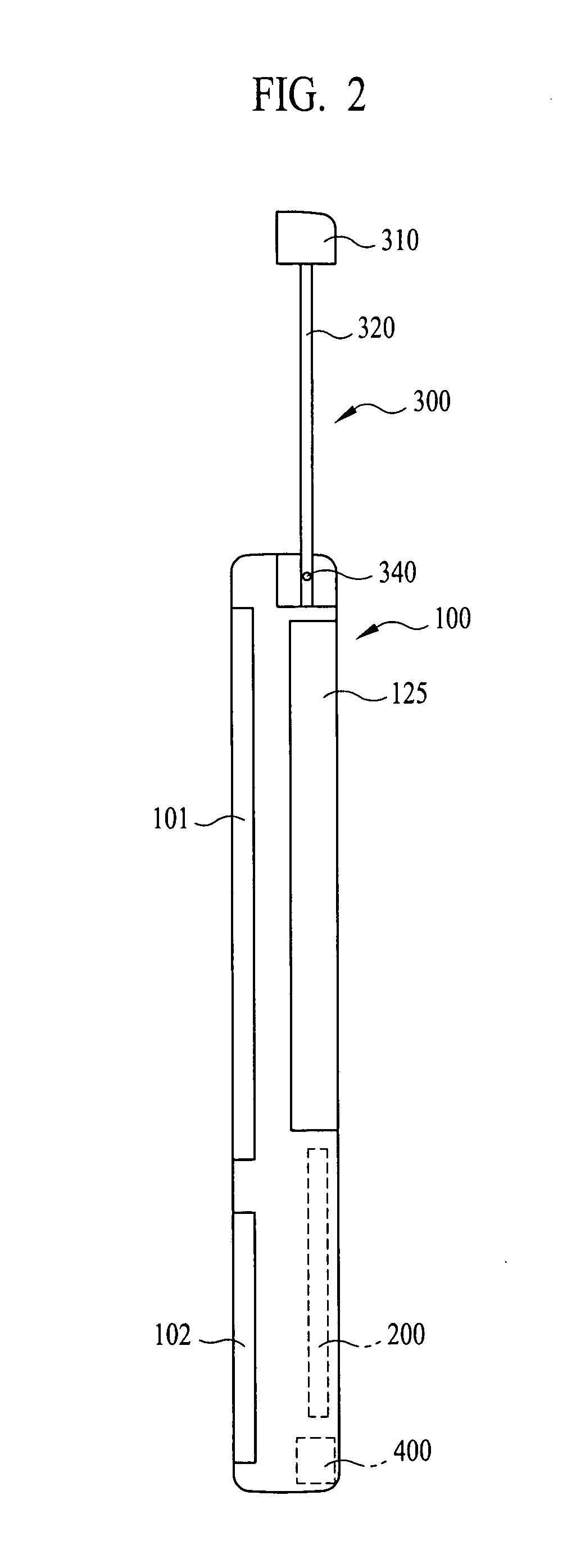
[0047] Although FIGS. 1 and 2 show a bar-type mobile communication terminal as an example of the present invention, the present invention may be applicable to other types identically.

[0048] As shown in FIGS. 1 and 2, a mobile communication terminal according to an embodiment of the present invention includes a body 100, a display window 101 provided on an upper front portion of the body 100 and a keypad 102 for inputting keys.

[0049] In addition, a battery 125 is provided on a rear upper portion of the body 100 and a PCB unit 200 (Printed Circuit Board unit) and an intenna unit 400 (inner antenna unit) are m...


PUM


Abstract

A mobile communication terminal according to the present invention includes a body, a PCB unit provided in a portion of the body for prescribed parts to be mounted, an antenna unit provided in another portion of the body, wherein a feeding point of the antenna unit is apart from the PCB unit, and a feeding connector which connects the feeding point with the PCB unit.

Description

[0001] This application claims the benefit of the Korean Patent Application No. 10-2006-0095486, filed on Sep. 29, 2006, which is hereby incorporated by reference as if fully set forth herein. BACKGROUND OF THE INVENTION [0002] 1. Field of the Invention [0003] The present invention relates to a mobile communication terminal. More particularly, the present invention relates to a mobile communication terminal that can improve mobile communication terminal usage environments. [0004] 2. Discussion of the Related Art [0005] Mobile communication terminals are typically configured of a case, a battery, a circuit substrate and an antenna. The case defines an exterior appearance of a mobile communication terminal and the battery supplies the power to the mobile communication terminal. Various parts are mounted on the circuit substrate. The antenna sends and receives predetermined signals to and from a base station or a satellite station. [0006] However, as a new structure is applied to a con...

Claims


Application Information

Patent Timeline
Patent Type & Authority Applications(United States)
IPC IPC(8): H04M1/03
CPCH04M1/026H01Q1/244H01Q1/24H04B1/38
Inventor LEE, SEONG CHEOL
Owner LG ELECTRONICS INC
Learn More