Intraocular Lens Implanting Device

a technology of intraocular lens and implanting device, which is applied in the field of implanting device, can solve the problems of damage to the optical surface the bifurcation of the plunger, and the hollowing of the middle, so as to achieve the effect of easy adjustment, less danger of the supporting parts of the intraocular lens being damaged, and easy adjustmen

Active Publication Date: 2008-04-10
HOYA CORP
View PDF101 Cites 72 Cited by
  • Summary
  • Abstract
  • Description
  • Claims
  • Application Information

AI Technical Summary

Benefits of technology

[0011] The present invention was designed in order to resolve the problems encountered with the conventional technique described above, and an object thereof is to provide an intraocular lens implanting device wherein the intraocular lens is prevented from rotating improperly when the intraocular lens is inserted into the eye, the intraocular lens can be safely and reliably inserted into the eyeball, and the device has an ophthalmic hooking function whereby the position of the intraocular lens can be adjusted after the intraocular lens has entered the eyeball. MEANS FOR SOLVING THESE PROBLEMS
[0025] According to the intraocular lens implanting device of the seventh aspect, the position of the intraocular lens is easily adjusted when the intraocular lens is inserted and implanted into the eyeball.

Problems solved by technology

However, the conventional technique described above has the following problems.
One problem arises from the distal end of the plunger being bifurcated and the middle being hollowed.
Specifically, since the plunger has a complicated shape having two protuberances for holding down the periphery of the intraocular lens, the pressure applied to the intraocular lens from the plunger when the intraocular lens is pushed out may concentrate in a particular region of the distal end of the plunger, and may damage the optical surface of the intraocular lens.
Another problem is that since the structure is complicated, production costs are high.
Another problem arises from the folding mechanism being attached to the cartridge itself.
The structure of the folding part therefore has restrictions, and it has been difficult to fold the intraocular lens into the desired shape.
If these positional relationships are inadequate or occasionally unstable, this causes problems in that a long time is spent setting the intraocular lens in place at a specific position, and a large burden is imposed on the operator and the patient.
Various shapes are possible for the supporting parts of the intraocular lens, such as plate shapes instead of barb shapes, but the same problems are encountered with an intraocular lens having plate-shaped supporting parts.

Method used


Image

  • Intraocular Lens Implanting Device
  • Intraocular Lens Implanting Device
  • Intraocular Lens Implanting Device

Examples


Embodiment Construction

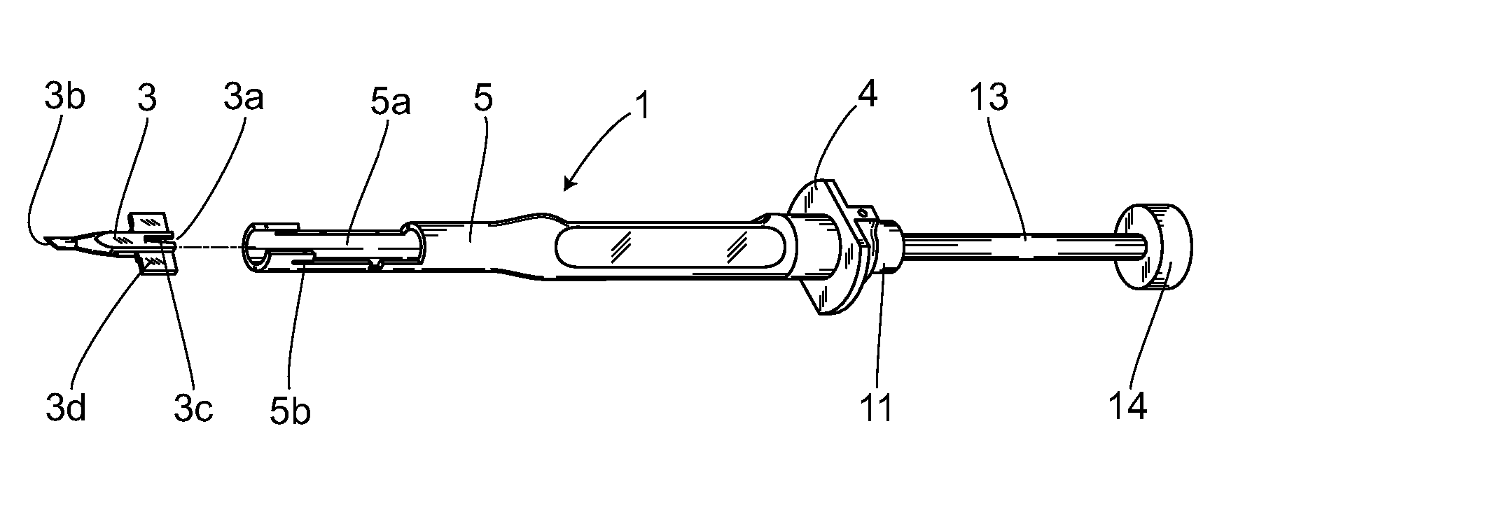
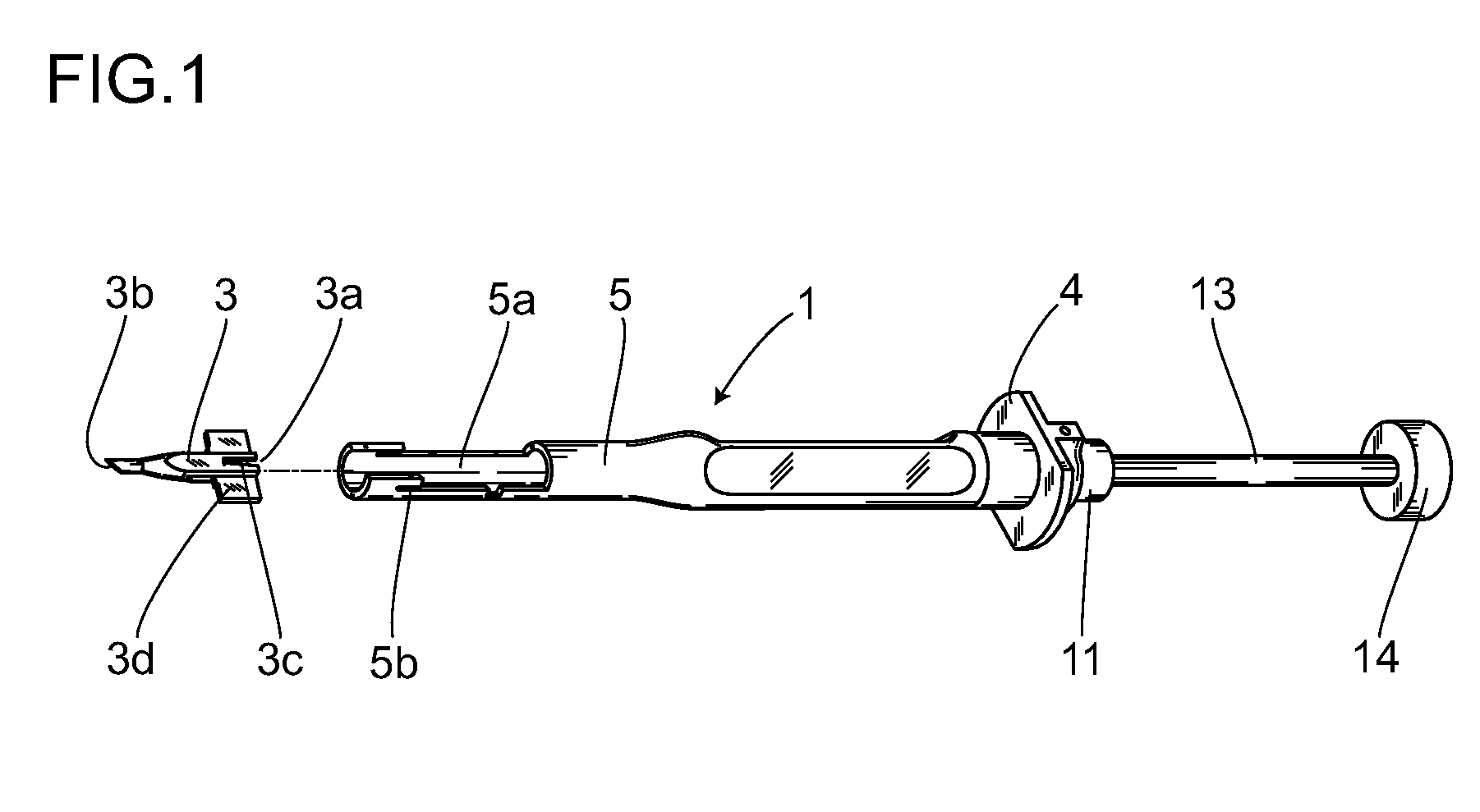
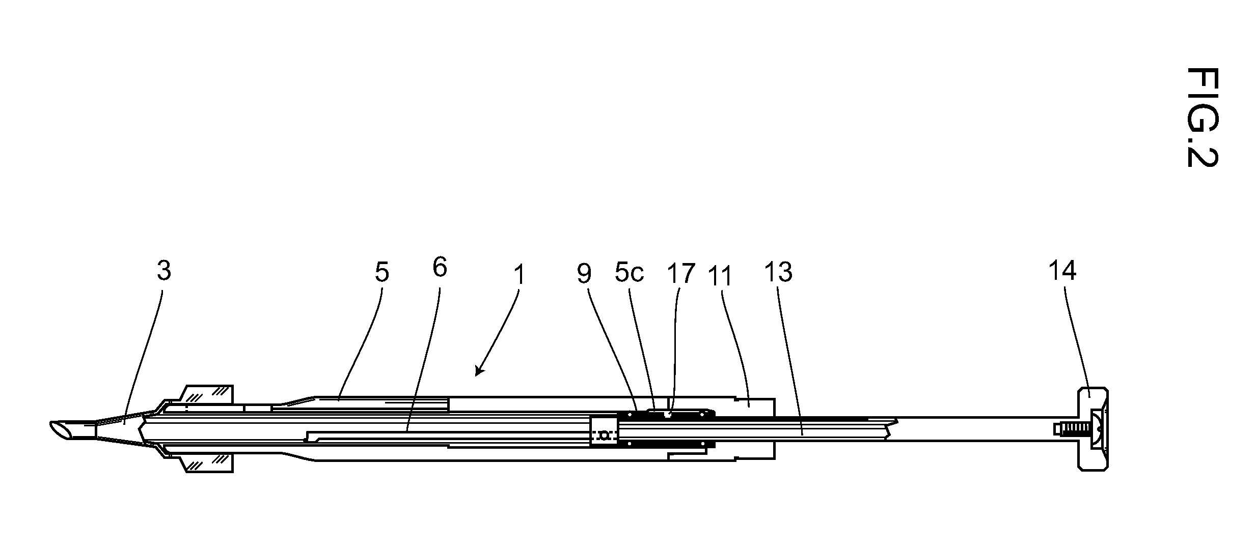
[0035] Embodiments of the present invention will now be described with reference to the drawings. FIG. 1 is an external perspective view of an intraocular lens implanting device relating to the present invention, and FIG. 2 is a cross-sectional view of the same. FIG. 3 is a partial exploded view of the intraocular lens implanting device.

[0036] First, an intraocular lens implanting device 1 to which the present invention is applied will be described. The general configuration of the intraocular lens implanting device 1 to which the present invention is applied has a cartridge 3 as a storage part for an intraocular lens 2, a cylindrical hand piece 5 as a main body in which the cartridge 3 is fastened at one end and a holding flange 4 is fixed in place at the other end, and a plunger 6 that passes through the hand piece 5 and is integrated with a push rod 13. A distal end 6a of the plunger 6 is configured from a base part 7 and a protuberance 8.

[0037] In the cartridge 3, the intraocu...


PUM


Abstract

An intraocular lens implanting device capable of inserting an intraocular lens surely in safety into an eyeball and having an ophthalmic hooking function capable of adjusting the position of the intraocular lens. The intraocular lens implanting device for inserting an intraocular lens into an eyeball through an incision in the eyeball tissue comprises a tubular main body, a storage part for the intraocular lens integrated with the main body or separated therefrom, and a plunger for pressing the intraocular lens placed in the containing section and discharging it into the eyeball, wherein the distal end of the plunger has a base part and a protuberance.

Description

CROSS REFERENCE TO RELATED APPLICATIONS [0001] This is a U.S. national phase application under 35 U.S.C. § 371 of International Patent Application No. PCT / JP2005 / 023246, filed Dec. 19, 2005 and claims the benefit of Japanese application 2004-377175 filed Dec. 27, 2004. The International Application was published in Japanese on Jul. 6, 2006 as International Publication No. WO 2006 / 070628 under PCT Article 21(2), the content of which are incorporated herein in its entirety.TECHNICAL FIELD [0002] The present invention relates to an implanting device for implanting an intraocular lens into an eyeball in place of a crystalline lens which has been extracted by cataract surgery; and specifically relates to an intraocular lens implanting device wherein a foldable intraocular lens is stored in a storage part, pressed in with a plunger, passed through an incision in the eyeball tissue, and implanted therein. BACKGROUND ART [0003] Artificial crystalline lenses are often implanted in the eye to...

Claims


Application Information

Patent Timeline
Patent Type & Authority Applications(United States)
IPC IPC(8): A61F9/007
CPCA61F2/1678A61F2/167
Inventor ISHII, KIYOSHIKUBOTA, KATSUTOSHI
Owner HOYA CORP
Why Eureka
Try Eureka