Weight-activated tying shoe

a technology of tying shoes and weight, applied in the field of shoes, can solve the problems of easy breakage of the mechanism, discomfort for users, and difficulty in tying shoes, and achieve the effect of releasing the tension of the mechanism

Active Publication Date: 2008-04-17
POWERLACE TECH
View PDF7 Cites 143 Cited by
  • Summary
  • Abstract
  • Description
  • Claims
  • Application Information

AI Technical Summary

Benefits of technology

[0017] The present invention provides an efficient way to tie shoes using the weight of the user who, upon sliding his foot inside the shoe, will depress a movable inner sole. This activates a side mechanism composed of a winch with a c

Problems solved by technology

Lacing shoes can be difficult or impossible for some people and several inventors have tried over the years to simplify the matter.
The large number

Method used


Image

  • Weight-activated tying shoe
  • Weight-activated tying shoe
  • Weight-activated tying shoe

Examples


Embodiment Construction

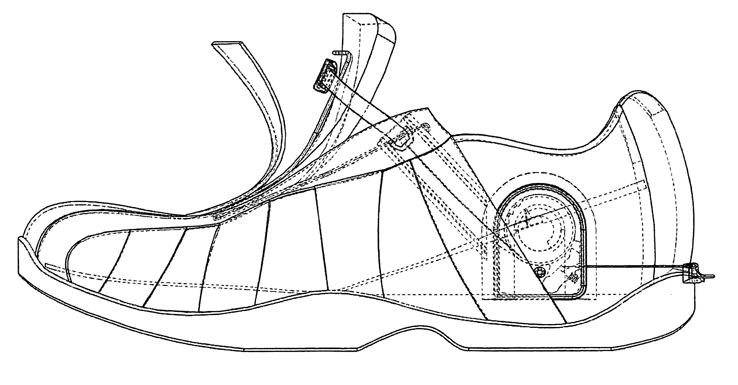
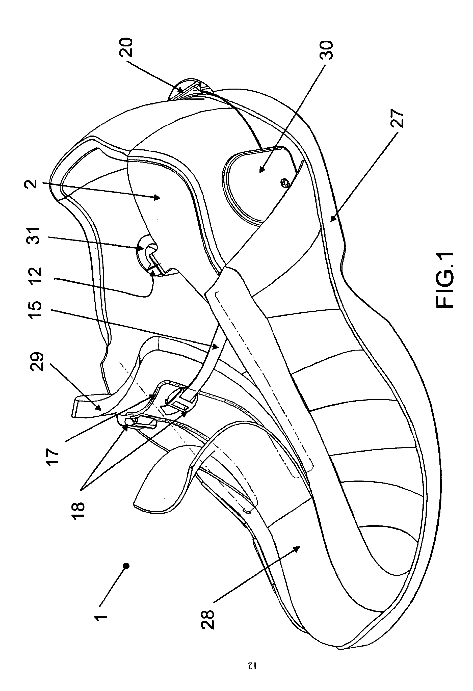
[0019]FIG. 1 See through orthogonal view of the shoe unlaced with the inner sole in an upward position.

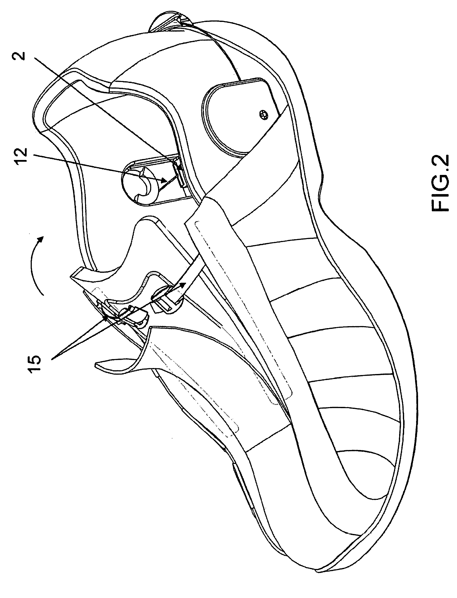
[0020]FIG. 2 See through orthogonal view of the shoe laced with the inner sole in a downward position.

[0021]FIG. 3 Orthogonal view of the interior mechanism with the inner sole in an upward position.

[0022]FIG. 4 Orthogonal view of the interior mechanism with the inner sole in a downward position.

[0023]FIG. 5 See through side elevation with the inner sole in an upward downward position.

[0024]FIG. 6 See through side elevation with the inner sole in a downward position. FIG. 7 Exploded view of the interior mechanism.

DETAILED DESCRIPTION OF THE PREFERRED EMBODIMENT

[0025]FIG. 1 A weight-activated lacing shoe (1) as illustrated is a conventional shoe having a sole (27) and a body (28), including a tongue (29) and a holding rod (17), which acts as a guide and keeps the tongue open when the side mechanisms (30-31) are released. The side mechanisms (30-31) are connected to the inner s...


PUM


Abstract

A weight-activated tying shoe wherein user who, upon sliding his foot inside the shoe, will depress a movable inner sole. This activates a side mechanism composed of a winch with a cable system used to close the tongue of the shoe towards the user's foot, thus lacing the shoe. The user simply uses his weight to activate the mechanism. Using his other foot, the user can move a pedal to release the mechanism's tension. Most of the mechanical components are located on both sides of the shoe body.

Description

CROSS-REFERENCE TO RELATED APPLICATIONS [0001] This application claims the benefit of provisional patent application Ser. No. 60 / 829,541, fitted 2006 Oct. 15 by the present inventor.BACKGROUND [0002] 1. Field of the Invention [0003] The invention relates generally to footwear, but more particularly to a weight-activated system intended to tie shoes, boots and snow shoes. [0004] 2. Prior Art [0005] Lacing shoes can be difficult or impossible for some people and several inventors have tried over the years to simplify the matter. [0006] U.S. Pat. No. 11,078,986 by the present inventor shows a self tying shoe on which the lacing device is activated by the weight of the user. The weight is transmitted to a mechanism located within the sole, underneath the foot. The large number of moving parts makes the mechanism vulnerable for breakage. In addition, the underneath location of the mechanism causes some discomfort to the user. For these reasons this patent has been abandoned. [0007] U.S. ...

Claims


Application Information

Patent Timeline
IPC IPC(8): A43C11/00
CPCA43B11/00Y10T24/37A43C11/165A43C11/008
Inventor LABBE, FREDERICK
Owner POWERLACE TECH
Why Eureka
Try Eureka