Access Cover for Piping or Vessel

a technology for access covers and piping or vessels, which is applied in the direction of wing fasteners, rigid containers, combination devices, etc., can solve the problems of labor and time-consuming procedures, and achieve the effect of easy and quick removal

Active Publication Date: 2008-04-24
TM INDAL SUPPLY
View PDF39 Cites 0 Cited by
  • Summary
  • Abstract
  • Description
  • Claims
  • Application Information

AI Technical Summary

Benefits of technology

[0010] It is another object of this invention to provide an access door, or cover, for the separator which is easily and quickly removable.

Problems solved by technology

This is a labor and time intensive procedure.

Method used


Image

  • Access Cover for Piping or Vessel
  • Access Cover for Piping or Vessel
  • Access Cover for Piping or Vessel

Examples


Embodiment Construction

[0028] A complete understanding of the invention will be obtained from the following description when taken in connection with the accompanying drawing figures wherein like reference characters identify like parts throughout.

[0029] For purposes of the description hereinafter, the terms “upper”, “lower”, “right”, “left”, “vertical”, “horizontal”, “top”, “bottom”, and derivatives thereof shall relate to the invention as it is oriented in the drawing figures. However, it is to be understood that the invention may assume various alternative variations and step sequences, except where expressly specified to the contrary. It is also to be understood that the specific devices and processes illustrated in the attached drawings, and described in the following specification, are simply exemplary embodiments of the invention. Hence, specific dimensions and other physical characteristics related to the embodiments disclosed herein are not to be considered as limiting.

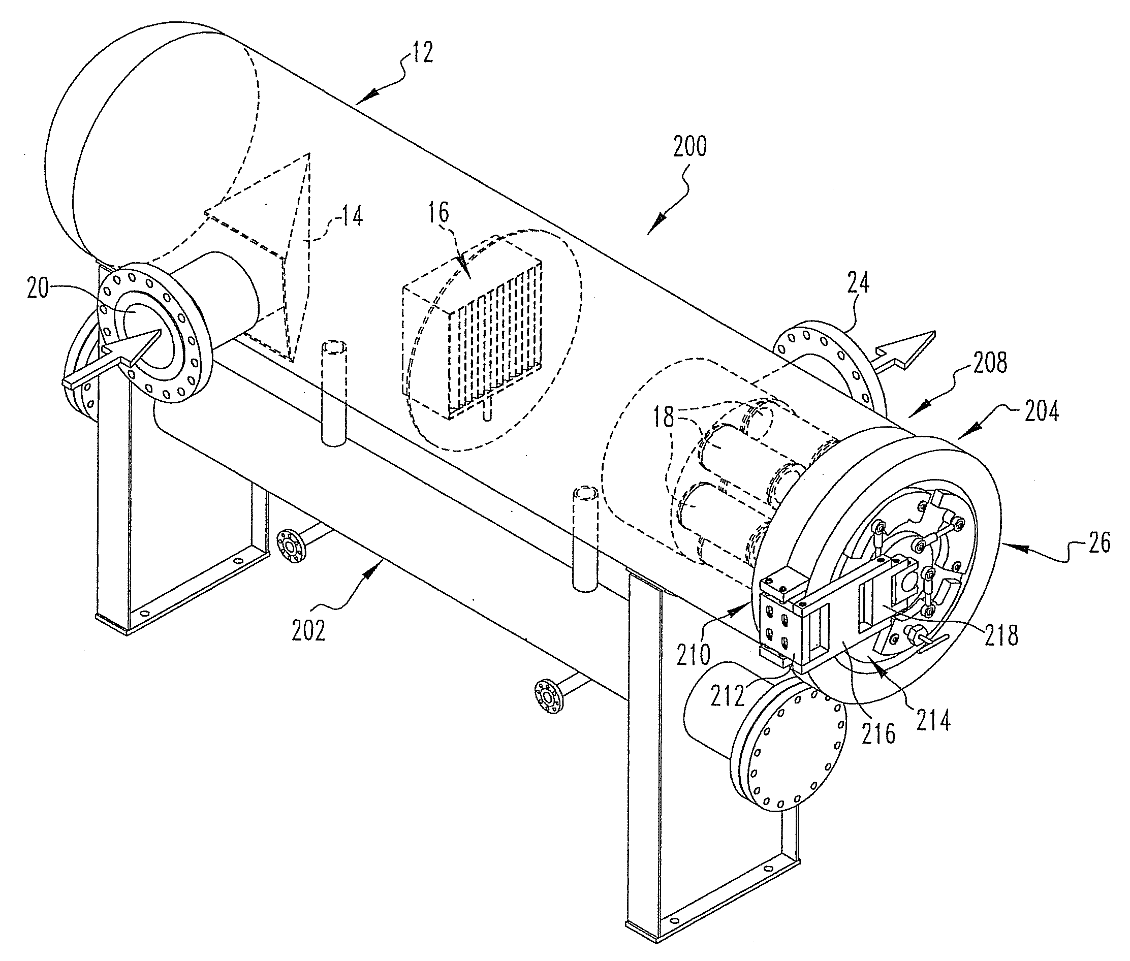
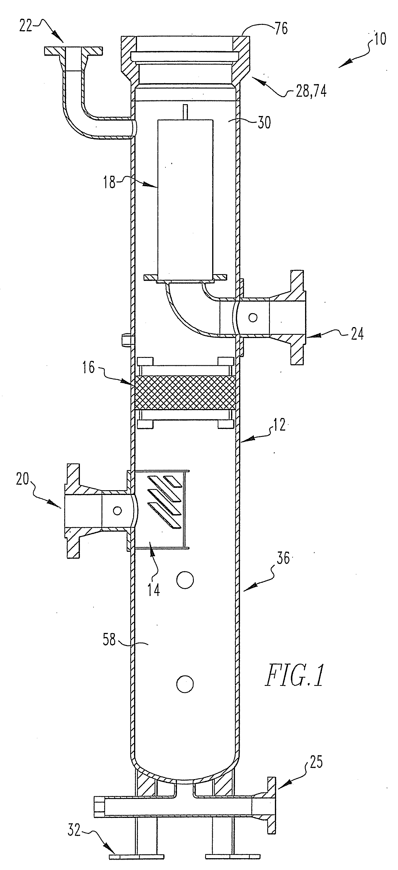
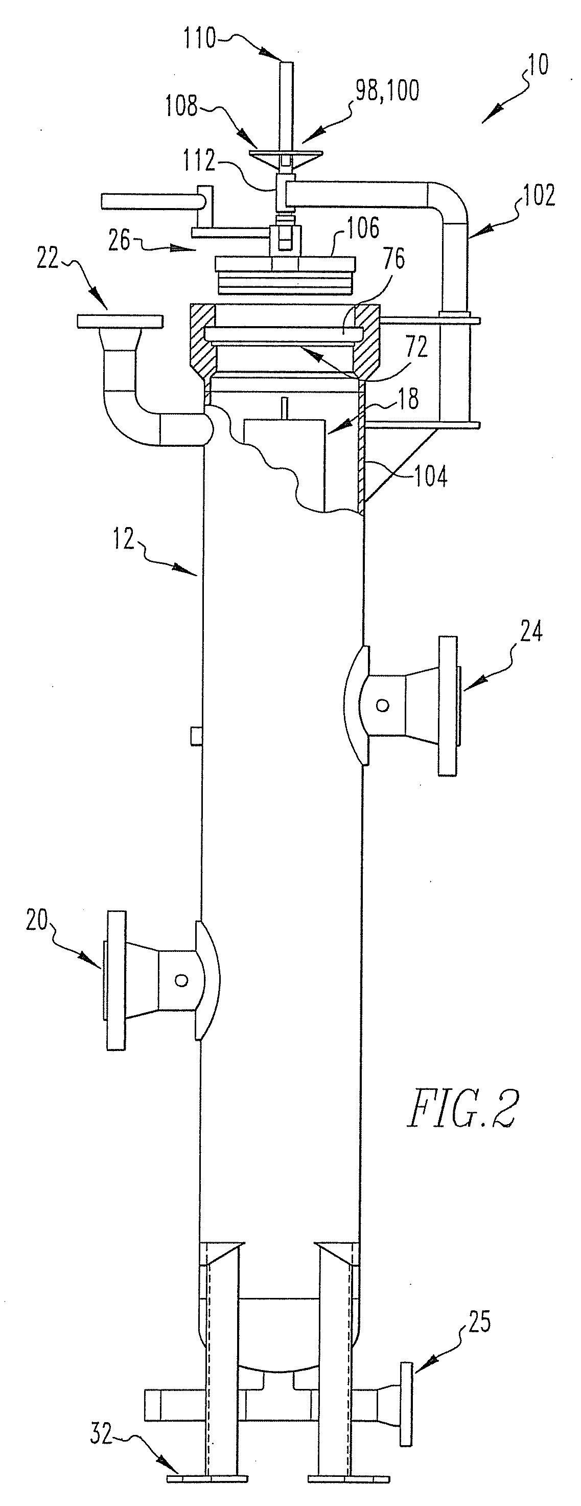
[0030] Referring to FIGS....


PUM

PropertyMeasurementUnit
velocityaaaaaaaaaa
radial velocityaaaaaaaaaa
thickaaaaaaaaaa

Abstract

Disclosed is a two or three phase separator including a centrifugal separator, a demister (if a three phase separator), and a filter contained within a housing. The filter uses an outside-in flow principle. The filter includes an inner layer or a center core that defines a hollow interior. An outer layer is positioned adjacent and surrounding the inner layer. The outer layer includes a re-enforcement layer, a first particle filter layer, a coalescer layer, and a second particle filter layer. An access cover of the separator includes a cover plug, an actuator cam, a plurality of idler cam plates, and a plurality of mechanisms. The access cover cooperates with an opening and an annular groove in the housing to close off and seal the separator.

Description

CROSS-REFERENCE TO RELATED APPLICATION [0001] This application is a divisional of and claims priority to U.S. patent application Ser. No. 10 / 414,056, filed Apr. 15, 2003, which claimed priority to U.S. Provisional Patent Application Ser. No. 60 / 373,016, filed Apr. 16, 2002.BACKGROUND OF THE INVENTION [0002] 1. Field of the Invention [0003] The present invention is directed to a separator for gas under pressure, and, more particularly, to a separator that filters the gas in a second or third phase. [0004] 2. Description of Related Art [0005] A separator is used to remove water and particulate materials from a pressurized gas, for example, a gas at approximately 280-1500 psig at 100° F. The gas may be natural gas, air, or any other gas. A three phase separator allows the gas to pass through three phases. Initially, in a first phase, the gas passes a centrifugal separator that removes large particles of liquid and debris and slows the velocity of the passing gas. Initial velocity of th...

Claims


Application Information

Patent Timeline
Patent Type & Authority Applications(United States)
IPC IPC(8): F16L55/10B01D35/30B01D39/14B01D46/02B01D50/00
CPCB01D50/002Y10T292/216Y10T292/0853Y10T292/205Y10T292/212F16J13/08B01D50/20
Inventor STEINER, CARL A.
Owner TM INDAL SUPPLY
Why Eureka
Try Eureka