Cut-sheet feeding apparatus, document-sheet feeding apparatus, and document-sheet reading apparatus

a feeding apparatus and document technology, applied in the direction of instruments, electrographic processes, transportation and packaging, etc., can solve the problems of cumbersome taking, damage to the document sheet, and inability to remove the document sheet from the feed path without damaging the document sh

Active Publication Date: 2010-03-30
BROTHER KOGYO KK
View PDF15 Cites 9 Cited by
  • Summary
  • Abstract
  • Description
  • Claims
  • Application Information

AI Technical Summary

Benefits of technology

[0021]This invention has been developed in view of the above-described situations, and it is an object of the invention to provide a cut-sheet feeding apparatus where a cut sheet caught in the cut-sheet feeding apparatus is easily and quickly removable.
[0023]The cut sheet may be a document sheet to be read by an image reading device or an image scanner, or a recording medium on which an image is to be recorded by an image recording device. The first and second portions can be relatively moved toward and away from each other to be switched between the opened state and the closed state. At least one of the first and second portions is movable relative to the other, that is, it may be arranged such that only one of the first and second portions is movable relative to the other, or such that the first and second portions are movable relative to each other. Where only one of the first and second portions is movable relative to the other, the movable one may be either of the first and second portions. In accordance with the relative movement between the first and second portions, the movable support member can be moved relative to the main body and between the operating position and the non-operating position. When the first and second portions are switched to their closed state, the movable-support-member driving portion moves the movable support member to the operating position thereof to elastically deform the elastic member, in order to press the second feed roller against the first feeder roller based on the elastic force, whereby the first and second feed rollers become capable of nipping and feeding the cut sheet. On the other hand, when the first and second portions are switched to their opened state, the movable-support-member driving portion allows the movable support member to move to the non-operating position thereof so as to separate the second feed roller from the first feed roller, thereby eliminating pressing contact between the first and second feed rollers and disabling to nip the cut sheet therebetween. Thus, the state of the first and second feed rollers is switched between a state to nip the cut sheet therebetween and another state to release the cut sheet or not to nip the cut sheet, and the switching is associated with relative movement between the first and second portions.
[0024]Thus associating switching in the state between the first and second feed rollers with relative movement between the first and second portions enables a user to remove a cut sheet that is caught while fed in the apparatus with a part of the cut sheet nipped between the first and second feed rollers, simply by relatively moving the first and second portions to switch their state to the opened state, without taking another action to only release the cut sheet from the nip between the first and second feed rollers. Hence, the invention simplifies an operation to solve a paper jam and reduces the time required for the operation.
[0026]The document feeding apparatus can be considered as a type of the cut-sheet feeding apparatus where the cut sheet is a document sheet an image whereon is to be read. The similar operation and effect as those of the above-described cut-sheet feeding apparatus can be obtained according to the document feeding apparatus. That is, the cover body is supported by the document reading table to be openable and closable relative to the document reading table. In the cover body, the protrusible member is disposed such that the position of the protrusible member is switchable between the inner position not to protrude therefrom and the outer position to protrude from the bottom surface of the cover body. The protrusible member is placed at the inner position when the cover body is closed, and placed at the outer position when the cover body is opened. When the cover body is closed relative to the document reading table, the protrusible member is moved to the inner position by being brought into contact with the document reading table. With the protrusible member moved to its inner position, the biasing member supported by the protrusible member biases the lower feed roller onto the upper feed roller. Thus, the pair of feed rollers, namely, the upper and lower feed rollers can nip and feed the document sheet. When the cover body is opened relative to the document reading table, the protrusible member is allowed to move off the document reading table, and moved to the outer position, by receiving an elastic force from the biasing member as well as by its own weight in an initial phase, and only by its own weight in a latter phase in which the elastic force from the biasing member is eliminated. When the protrusible member is moved to the outer position, the lower feed roller moves downward and separates from the upper feed roller, with the shaft of the lower feed roller moving downward relative to the bearing member, by a weight of its own and the lower feed roller. Thus, pressing contact between the pair of feed rollers, namely, the upper and lower feed rollers is eliminated and the upper and lower feed rollers are disabled to nip the document sheet therebetween. In this way, the pair of feed rollers is switched between a state to nip the document sheet therebetween and another state to release the document sheet or not to nip the document sheet, and the switching is associated with opening and closing of the cover body relative to the document reading table.

Problems solved by technology

Thus, it is impossible to remove the document sheet from the feed path without damaging the document sheet, unless the pressing contact between the feeder roller and the pinch roller is eliminated.
However, when a document sheet caught at or around the open portion disposed at the bottom surface of the document cover should be removed, a user may feel that it is cumbersome to take the above-mentioned two actions, or may not know the way to eliminate the pressing contact between the feeder roller and the pinch roller, or the way to separate the feeder roller and the pinch roller from each other.
In the former case, that is, when the user feels that taking the two actions is cumbersome, he or she may first open the document cover to expose a part of the document sheet to the exterior, and then forcibly pull out the document sheet pinched between the feeder roller and the pinch roller.
The forcibly pulling out the document sheet pinched between the feeder roller and the pinch roller that are held in pressing contact with each other may damage the document sheet.
In the latter case, that is, when the user does not know the way to eliminate the pressing contact between the feeder roller and the pinch roller, it takes much time to remove the caught document sheet.

Method used


Image

  • Cut-sheet feeding apparatus, document-sheet feeding apparatus, and document-sheet reading apparatus
  • Cut-sheet feeding apparatus, document-sheet feeding apparatus, and document-sheet reading apparatus
  • Cut-sheet feeding apparatus, document-sheet feeding apparatus, and document-sheet reading apparatus

Examples


Embodiment Construction

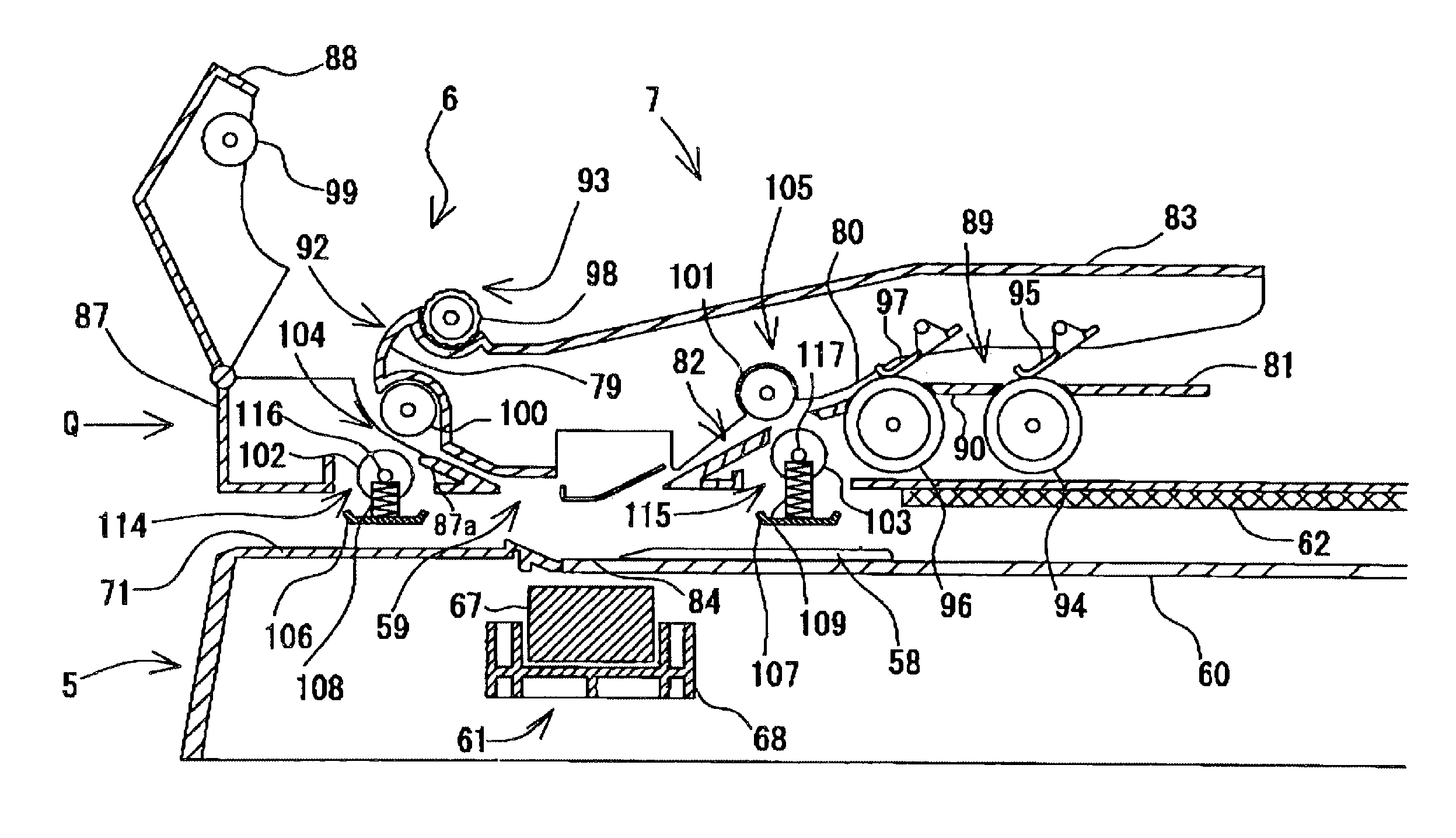
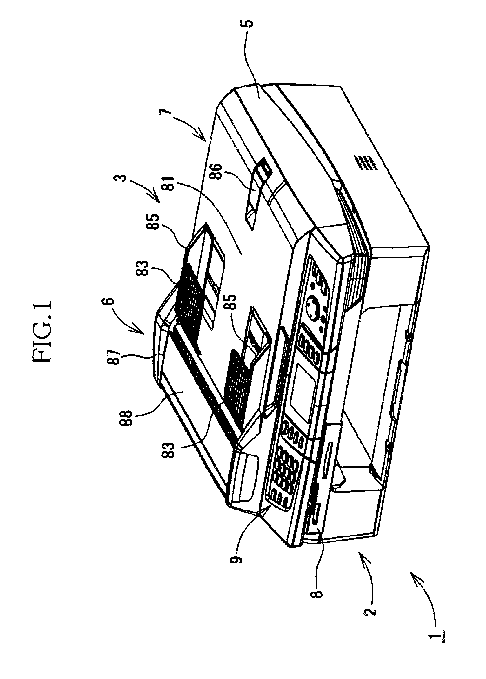
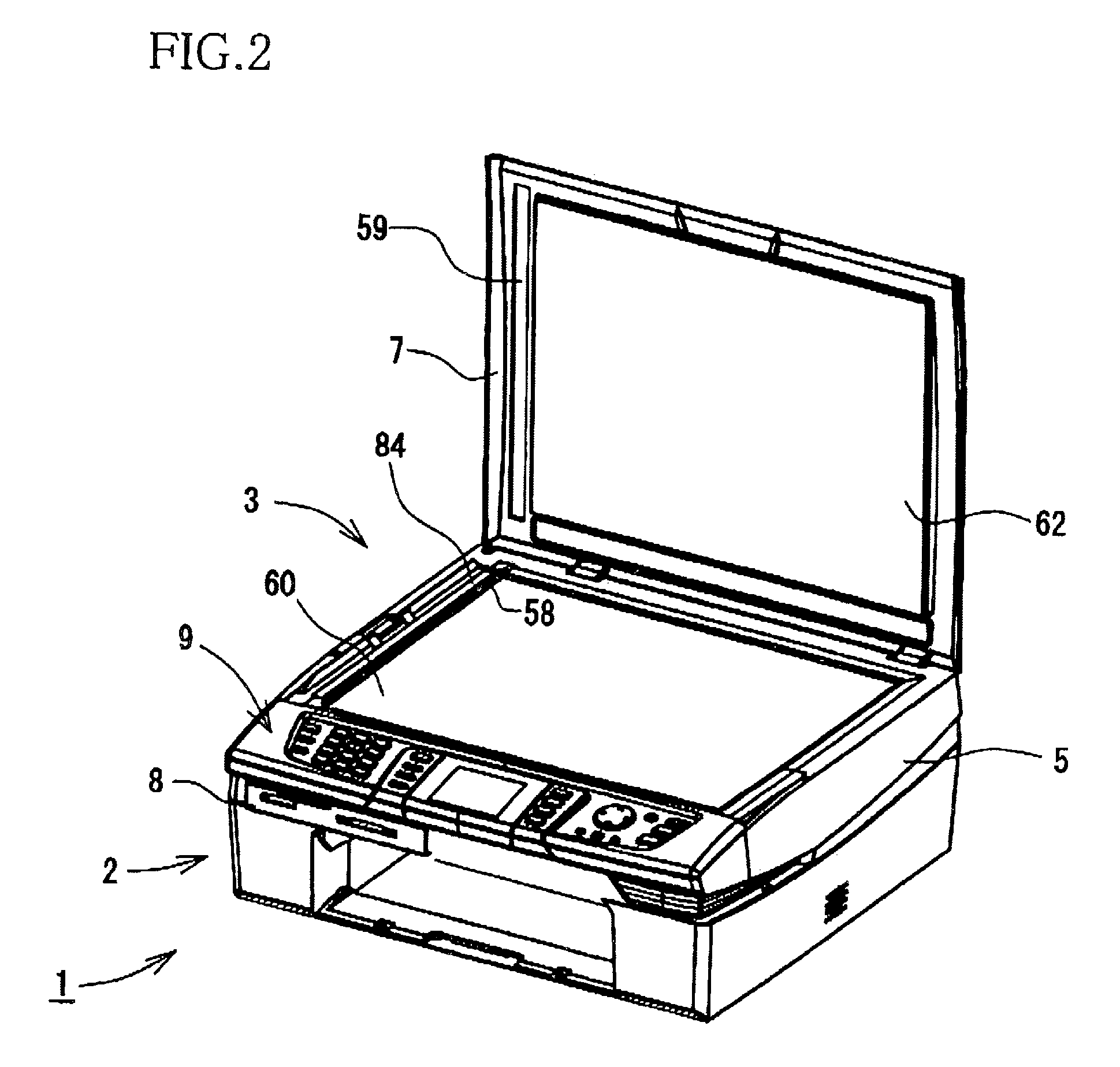
[0041]Hereinafter, there will be described a multifunctional apparatus including an ADF (Automatic Document Feeder) according to one embodiment of the invention, by referring to the accompanying drawings.

[0042]Referring first to FIG. 1, reference numeral 1 generally denotes the multifunctional apparatus that includes the ADF 6 according to an embodiment of the invention. The multifunctional apparatus 1 may be referred to as MFD (Multi Function Device) that is an apparatus having two or more of a printer function, a scanner function, a copier function, a facsimile function, and other functions. The multifunctional apparatus 1 integrally includes a printer portion 2, a scanner portion 3, a document cover body 7, an operator panel 9, and a slot portion 8. The printer portion 2 constitutes a lower portion of the multifunctional apparatus 1, and the scanner portion 3 is disposed over the scanner portion 3. The document cover body 7 is disposed over the scanner portion 3. The operator pan...


PUM


Abstract

A document feeding apparatus in a cover body supported by a document reading table whose upper surface is at least partially constituted by a platen glass. The cover body is openable and closable relative to the table and covers the glass when closed. The apparatus feeds a document sheet along a feed path from at a document setting portion and to a document ejecting portion. The apparatus comprises: an upper and a lower feed roller that are disposed along the path to pinch and feed the sheet; a bearing member supporting a shaft of the lower roller such that the lower roller is movable onto and away from the upper roller; a protrusible member disposed in the cover body and below the lower roller to be movable between an outer position to protrude from a bottom of the cover body and an inner position not to protrude therefrom, the protrusible member being placed at the outer position when the cover body is open, and at the inner position by the document reading table when the cover body is closed; and a biasing member supported by the protrusible member and biasing the lower roller toward the upper roller, such that when the protrusible member is at the outer position, the lower roller is off the upper roller, and when the protrusible member is at the inner position, the lower roller is in pressing contact with the upper roller.

Description

INCORPORATION BY REFERENCE[0001]The present application is based on Japanese Patent Application No. 2005-240922, filed on Aug. 23, 2005, the contents of which are incorporated herein by reference.BACKGROUND OF THE INVENTION[0002]1. Field of the Invention[0003]The present invention relates to a cut-sheet feeding apparatus, a document feeding apparatus, and a document-sheet reading apparatus.[0004]2. Description of Related Art[0005]There is widely known an image, processing apparatus, such as a scanner, a copier, a facsimile machine, or a multifunction apparatus having two or more of a scanner function, a copier function, and a facsimile function, which includes a cut-sheet feeding apparatus that automatically picks up a plurality of cut sheets such as recording sheets or document sheets set on a setting portion or a supply tray to one by one supply the cut sheets into a feed path. Each cut sheet is then fed along the feed path down to an ejecting portion or a catch tray, onto which t...

Claims


Application Information

Patent Timeline
Patent Type & Authority Patents(United States)
IPC IPC(8): H04N1/04B41J3/00B65H5/22
CPCB65H5/062B65H29/14H04N1/00543H04N1/00559H04N1/0057H04N1/00588H04N1/00591H04N1/00602H04N1/00615H04N1/12B65H2404/144
Inventor IWAGO, TOSHITAKA
Owner BROTHER KOGYO KK
Why Eureka
Try Eureka