Compiler and logic circuit design method

a logic circuit and compiler technology, applied in the field of compiler and logic circuit design methods, can solve problems such as complicated program descriptions, method is difficult to make such a description, and complicated job involvemen

Inactive Publication Date: 2008-04-24
RENESAS ELECTRONICS CORP
View PDF2 Cites 15 Cited by
  • Summary
  • Abstract
  • Description
  • Claims
  • Application Information

AI Technical Summary

Benefits of technology

[0007] An object of the present invention is to provide a compiler which can automatically generate hardware descriptions from program descriptions that explicitly indicate clock boundaries.
[0008] Another object of the invention is to provide a compiler which can easily generate the program descriptions or circuit descriptions of a circuit capable of a pipeline operation attended with a stall operation.
[0009] Still another object of the invention is to provide a logic circuit design method which can design a circuit capable of a pipeline operation attended with a stall operation.
[0015] Since functions can be designed at the program level without caring about the state machines, the quantity of descriptions is decreased, so that the design method contributes, not only to shortening the term of a development, but also to enhancing a quality.

Problems solved by technology

By way of example, it must be described that, when a certain condition has held, a circuit operation is begun at an intermediate position of a circuit operation executed in a preceding cycle, but the method is difficult of making such a description.
It has been found out by the inventors that, especially when a circuit which performs a pipeline operation attended with a stall operation is described by the method stated in Patent Document 1, a complicated job might be involved, program descriptions becoming complicated.
However, there is no means for explicitly affording clock boundaries, and descriptions at a cycle precision cannot be directly made.
It has been found out by the inventors that, especially a circuit which performs a pipeline operation attended with a stall operation can be described by the method stated in Patent Document 2, but that a complicated job might be involved, program descriptions becoming complicated.

Method used


Image

  • Compiler and logic circuit design method
  • Compiler and logic circuit design method
  • Compiler and logic circuit design method

Examples


Embodiment Construction

[0098]>

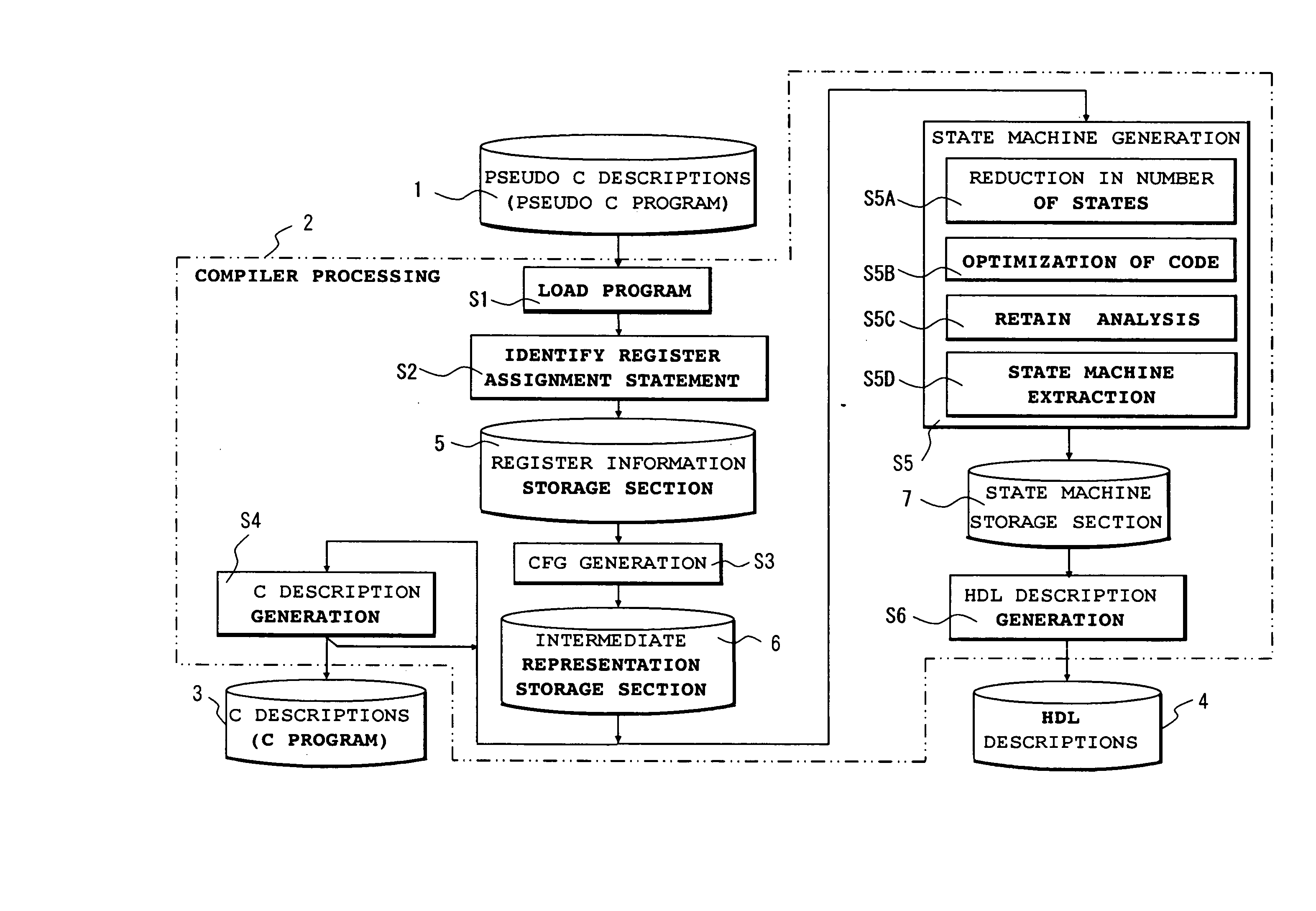
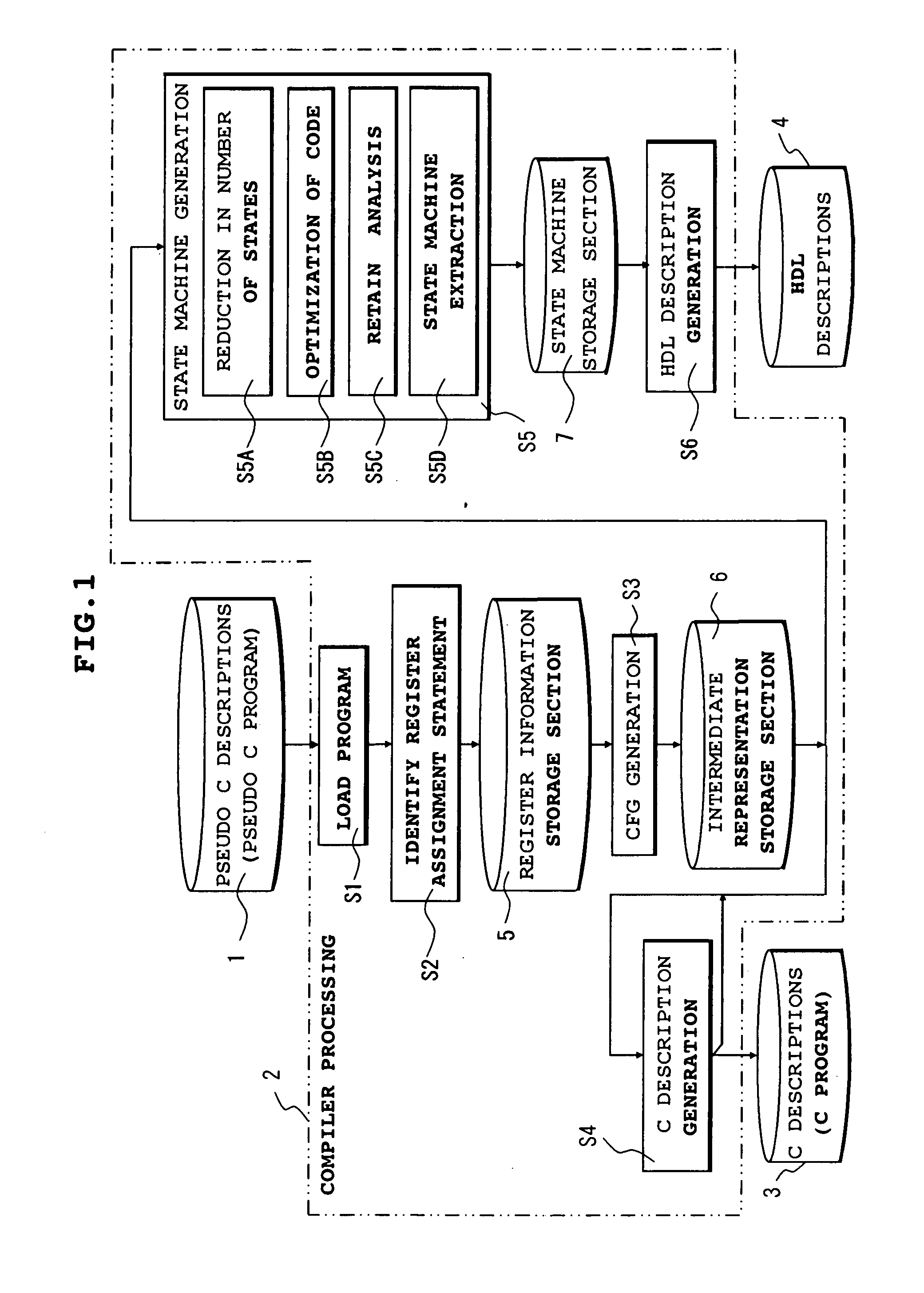
[0099] A logic circuit design method according to the present invention is exemplified in FIG. 1. The design method shown in the figure is broadly classified into the creation of pseudo C descriptions (pseudo C program) 1, and compiler processing 2 for the pseudo C program 1. In the compiler processing 2, the pseudo C program 1 is converted into a pseudo C program (stored in a storage section 5) whose transformed assignment statement is a register assignment description, and executable C descriptions (C program) 3. Besides, the C program 3 is converted into HDL (Hardware Description Language) descriptions 4 of RTL (Register Transfer Level) or the like.

[0100] The pseudo C program 1 is a program which includes a clock boundary description (also written “clock boundary” simply) capable of specifying a circuit operation at a cycle precision, and a register assignment statement, and which is capable of parallel descriptions at a statement level. The expression “pseudo C descripti...


PUM


Abstract

A compiler in which pseudo C descriptions (1) that are capable of describing parallel operations at a statement level and at a cycle precision by clock boundaries and register assignment statements are input, the register assignment statements are identified (S2), so as to generate executable C descriptions (3), to extract state machines having undergone reductions in the numbers of states, and to decide whether or not a loop to be executed in the 0th cycle is existent (S5), and if the loop is nonexistent, circuit descriptions (4) that are capable of being logically synthesized are generated. Thus, the pseudo C descriptions in which the clock boundaries are explicitly inserted into the C descriptions are input, and the pseudo C descriptions which permit the register assignment statements to be described in parallel at the statement level are input, so that a pipeline operation attended with a stall operation can be represented.

Description

FIELD OF THE INVENTION [0001] The present invention relates to technology in which program descriptions for a simulation or circuit descriptions for specifying hardware are automatically generated from program descriptions. By way of example, it relates to technology which is effective when applied to the design of a logic circuit executing a pipeline operation, for example, a logic circuit such as CPU (Central Processing Unit). BACKGROUND OF THE INVENTION [0002] There has been technology for generating the circuit descriptions of a digital circuit with a program language. A technique stated in Patent Document 1 includes a collective assignment part according to which variables are classified into ones indicative of registers and ones indicative of the inputs of the registers, whereupon the second variables are collectively assigned to the first variables after processing in a module part. A technique stated in Patent Document 2 consists in that parts which are sequentially controll...

Claims


Application Information

Patent Timeline
Patent Type & Authority Applications(United States)
IPC IPC(8): G06F17/50G06F9/45
CPCG06F17/5045G06F30/30
Inventor TANIMOTO, TADAAKIKAMADA, MASURAO
Owner RENESAS ELECTRONICS CORP
Why Eureka
Try Eureka