Device for winding suspension cord of blind

a technology for suspension cords and blinds, which is applied in the direction of door/window protective devices, shutters/movable grilles, wing arrangements, etc., can solve the problems of unsuitable large-size blinds or long suspension cords, complicated structure for winding suspension cords, and limited space for roller shade bars to move in an axial direction

Inactive Publication Date: 2008-05-01
NIEN MADE ENTERPRISE CO LTD
View PDF16 Cites 18 Cited by
  • Summary
  • Abstract
  • Description
  • Claims
  • Application Information

AI Technical Summary

Benefits of technology

[0009]In view of the aforementioned problems needed to be solved, the device for winding a suspension cord of a blind provided by the present invention may arrange the suspension cord on a cord spool in sequence and can compensate the torque of a power resilient element for the blinds of different sizes.

Problems solved by technology

However, the structure for winding the suspension cords is complicated and the space for the roller shade bar to move in an axial direction is limited.
Therefore, such structure is unsuitable for a blind with a large size or long suspension cords.
Spiral grooves formed in the surface of the cord spool must increase the manufacturing cost.
However, there is no guide mechanism between the suspension cord and the cord spool, and the portion with a taper is far away from the position where the suspension cord corresponds to the cord spool.
As such, the suspension cord will be easily seized during the later stage of winding the suspension cord due to the absence of the guide of the taper, resulting in the non-smoothness in winding the suspension cord.
The attenuated torque of the spring housing cannot be balanced out with the torque applied to the cord spool by the gravity of the blind.
Therefore, the blind cannot be fixed due to the gravity thereof, and such problem cannot be solved until the spring housing is replaced.
Thus, the gravity of the blind is various, while the torque of the spring housing is constant, resulting in that the spring housing cannot be completely suitable for the blinds with different sizes.
However, the device for winding a suspension cord without using the spring housing often suffers from the problem of the non-smoothness in winding the suspension cord.

Method used


Image

  • Device for winding suspension cord of blind
  • Device for winding suspension cord of blind
  • Device for winding suspension cord of blind

Examples


first embodiment

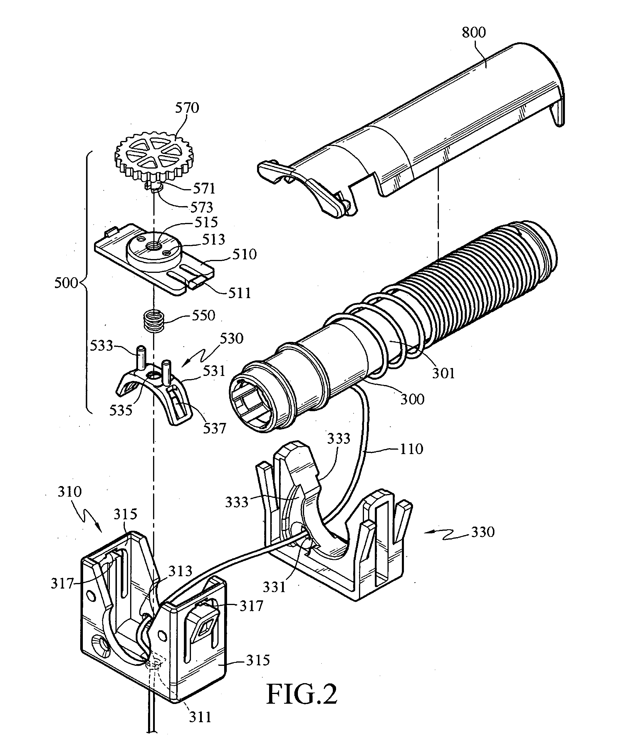
[0031]Please refer to FIGS. 4A and 4B of a schematic view of the connection and a schematic view of the operation of the adjusting means and the pedestal in the present invention. As shown in FIGS. 2, 4A, and 4B, the adjusting means 500 includes a fixed plate 510, a tablet 530, a resilient element 550, and a knob. The fixed plate 510 has a bump 511 extending from both ends thereof. A hole 317 is respectively opened in the two side walls 315 of the pedestal 310, such that the bumps 511 of the fixed plate 510 is buckled in the holes 317 and then the fixed plate 510 is buckled in the pedestal 310. A through hole 513 is opened in the fixed plate 510 along the side wall 315. The tablet 530 is an arc plate 531, and a sliding bar 533 extends from one side of the arc plate 531. The sliding bar 533 penetrates through the through hole 513, such that the tablet 530 may slide up and down with respect to the fixed plate 510. When the fixed plate 510 is fixed on the pedestal 310, the tablet 530 p...

second embodiment

[0037]Please refer to FIG. 5 of a schematic view of the connection of the adjusting means and the pedestal in the present invention. As shown in FIG. 5, the fixed plate 510 and the pedestal 310 are integrally formed. Therefore, a through hole 318 and a bolt hole 319 are opened in one side wall of the pedestal 310 opposite to the adjusting means 500, and the relationship between the pedestal 310 and the adjusting means 500 is the same as that in the above-mentioned embodiment and will not be described any more.

third embodiment

[0038]Please refer to FIG. 6 of a schematic view of the connection of the adjusting means and the pedestal in the present invention. As shown in FIG. 6, a through hole 318 and a bolt hole 319 are formed in one side of the pedestal 310. The adjusting means 500 includes a tablet 530 and a knob 570. The tablet 530 has a sliding bar 533 extending from one end thereof, wherein the sliding bar 533 passes through the through hole 318, such that the tablet 530 is fitted on the pedestal 310 and may slide vertically, and the lower end of the tablet 530 presses against the surface of the cord surface 300. The knob 570 has a screw axis 571 extending from one end thereof, and the screw axis 571 is screw-connected to the bolt hole 319 and pivoted to the tablet 530 with the back end thereof. A collar 575 is further disposed above the tablet 530 to prevent the tablet 530 from dropping outside the rotating shaft 571. As such, the tablet 530 may adjust the pressure generated when the tablet 530 press...


PUM


Abstract

A device for winding a suspension cord of a blind is provided to wind a suspension cord disposed on a blind. The suspension cord is spirally wound about a cord spool through a spiral guide groove of a guide component, and then arranged along the cord spool in sequence. Additionally, when the cord spool is connected to a power resilient element as a power source of rotation, friction force is applied to the cord spool through an adjusting component to adjust the output torque of the cord spool, such that the torque applied to the cord spool by the power resilient element can be balanced out with the torque applied to the cord spool by the gravity of the blind.

Description

BACKGROUND OF THE INVENTION[0001]1. Field of Invention[0002]The present invention relates to a device for winding a suspension cord of a blind, and more particularly to a device for winding a suspension cord of a blind, which arranges the suspension cord on a cord spool in sequence through a guide means and adjusts the output torque of the cord spool by using the friction force applied to the cord spool by an adjusting means.[0003]2. Related Art[0004]A cordless blind utilizes a spring housing as a power source, and the torque applied to a cord spool by the spring housing is balanced out with the torque applied to the cord spool by the gravity of the blind. Therefore, the blind can be kept at any position.[0005]The relevant technology has been disclosed in some U.S. patents. U.S. Patent Publication No. 5,706,876 has disclosed that a suspension cord is wound when a roller shade bar is rotated, and a power spring is disposed in the roller shade bar to generate the power of rotation for...

Claims


Application Information

Patent Timeline
Patent Type & Authority Applications(United States)
IPC IPC(8): A47H5/00
CPCE06B9/322E06B2009/3227E06B2009/3225
Inventor NIEN, MINGWEN, YU-CHECHANG, CHIH-YAOPON, DAVIDREN, JUDKINS
Owner NIEN MADE ENTERPRISE CO LTD
Why Eureka
Try Eureka