Method for recovering energy from the combustion engine during changing up, and control device for carrying out the method

A control device, a technology for an internal combustion engine, applied in the field of recovering the energy of the internal combustion engine during upshifting and for implementing the control device, capable of solving problems such as poor exhaust gas values

Pending Publication Date: 2020-11-27
MAGNA PT B V & CO KG
View PDF5 Cites 0 Cited by
  • Summary
  • Abstract
  • Description
  • Claims
  • Application Information

AI Technical Summary

Problems solved by technology

This leads to worse exhaust gas values, since the combustion is no longer ideal

Method used

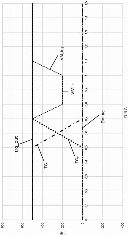
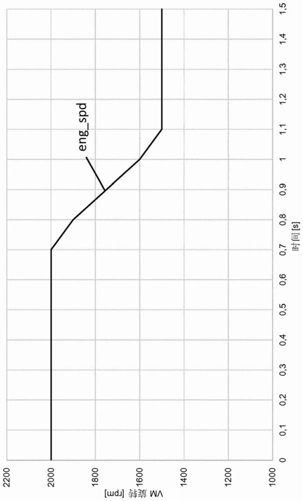
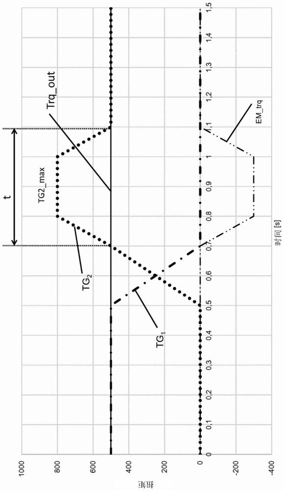

Image

  • Method for recovering energy from the combustion engine during changing up, and control device for carrying out the method
  • Method for recovering energy from the combustion engine during changing up, and control device for carrying out the method
  • Method for recovering energy from the combustion engine during changing up, and control device for carrying out the method

Examples


Embodiment Construction

[0024] in Figure 4 Schematically shows an integrated hybrid technology solution with an electric motor EM in a dual-clutch transmission. As an additional electric machine, the system has a starter generator 13.

[0025] The technical solution according to the present invention can be implemented not only as a hybrid dual-clutch transmission, but also as a starter generator.

[0026] The power train 10 includes an internal combustion engine (VM) VM, which is connected to a starter generator 13. In addition, the power train 10 includes a dual-clutch transmission 14 whose output side is connected to a differential 16. The differential 16 distributes the driving power to the left and right driving wheels 18L, 18R.

[0027] The dual clutch transmission 14 includes a first friction clutch 30 and a first sub-transmission TG 1 . First sub-transmission TG 1 For example, it includes gears N, 1, 3, 5, etc., which can be engaged and disengaged by means of a schematically shown shift clutch 3...


PUM


Abstract

The invention relates to a method for recovering kinetic energy from a combustion engine (VM) by reducing the speed of the combustion engine (VM) for a predetermined time (t) during changing up of a gearbox (14) in a vehicle and converting the kinetic energy of the rotation of the combustion engine (eng_spd) or of a drive unit into electrical energy by at least one electric motor (EM, 13).

Description

Technical field [0001] The invention relates to a method for recovering the energy of an internal combustion engine during an upshift and a control device for executing the method. Background technique [0002] In the field of automotive technology, there has been a trend toward hybrid vehicles in recent years. In hybrid vehicles, driving power can be provided by means of an internal combustion engine and by means of an electric motor. Here, there is generally a difference between so-called mild hybrid applications. In mild hybrid applications, the motor can only be used as a separate drive source for a short time, or mainly used as a booster drive. In contrast, in the so-called range extender-powertrain, the electric motor is used as the main drive engine, and the internal combustion engine is driven to charge the battery. In terms of the layout of this powertrain, there is the feasibility as follows: the internal combustion engine electric drive machine is arranged upstream of...

Claims


Application Information

Patent Timeline
IPC IPC(8): B60K6/48B60W10/02B60W10/06B60W10/08B60W10/113B60W20/30
CPCB60K6/48B60K2006/4816B60W10/02B60W10/06B60W10/08B60W10/113B60W20/30B60W2710/0644Y02T10/62Y02T10/92
Inventor 雅克·普罗斯特
Owner MAGNA PT B V & CO KG
Why Eureka
Try Eureka