
Heat-Generating Element for an Electric Heating Device and Method for the Manufacture of the Same

Active Publication Date: 2008-05-01
CATEM
View PDF5 Cites 37 Cited by
  • Summary
  • Abstract
  • Description
  • Claims
  • Application Information

AI Technical Summary

Benefits of technology

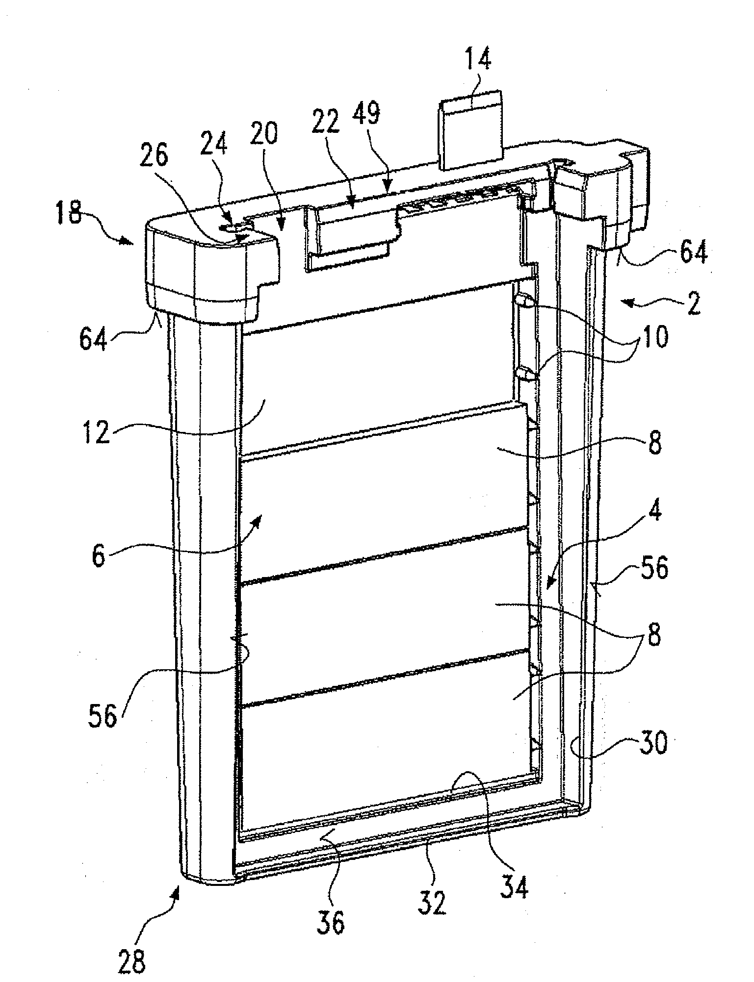
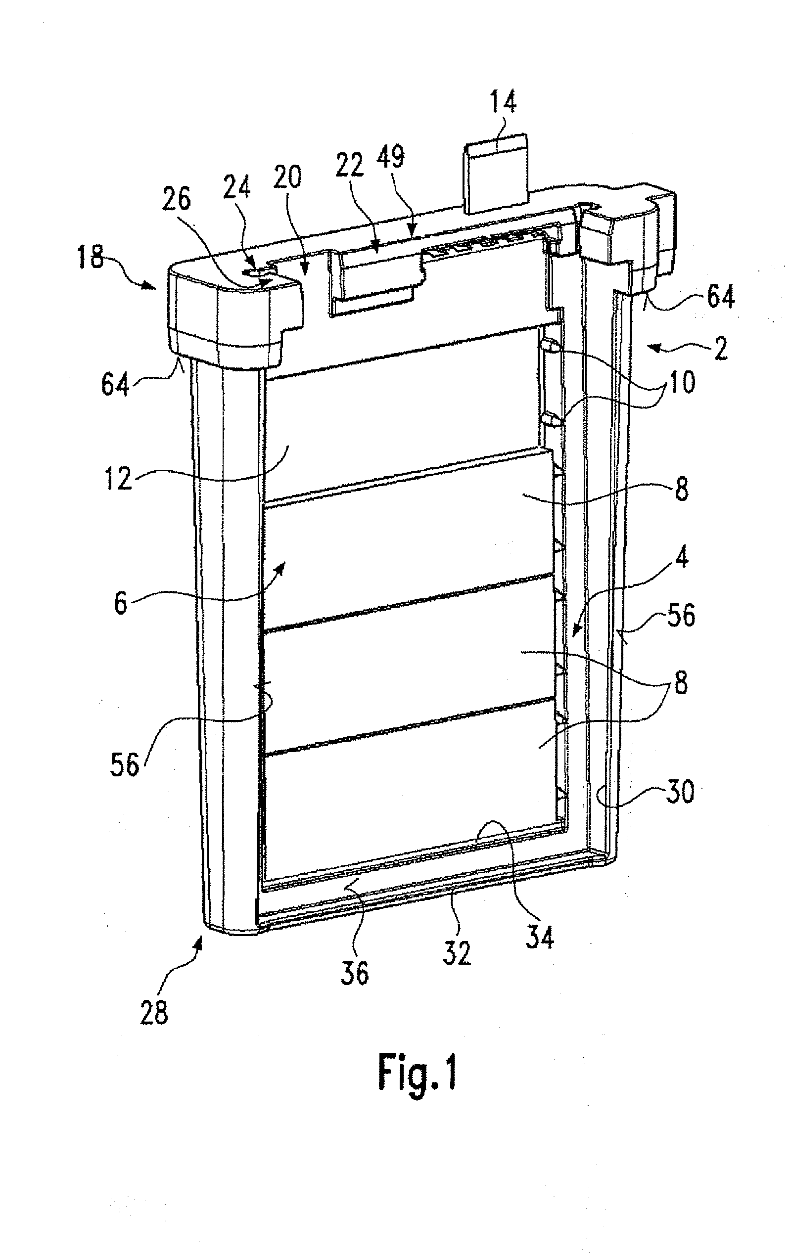
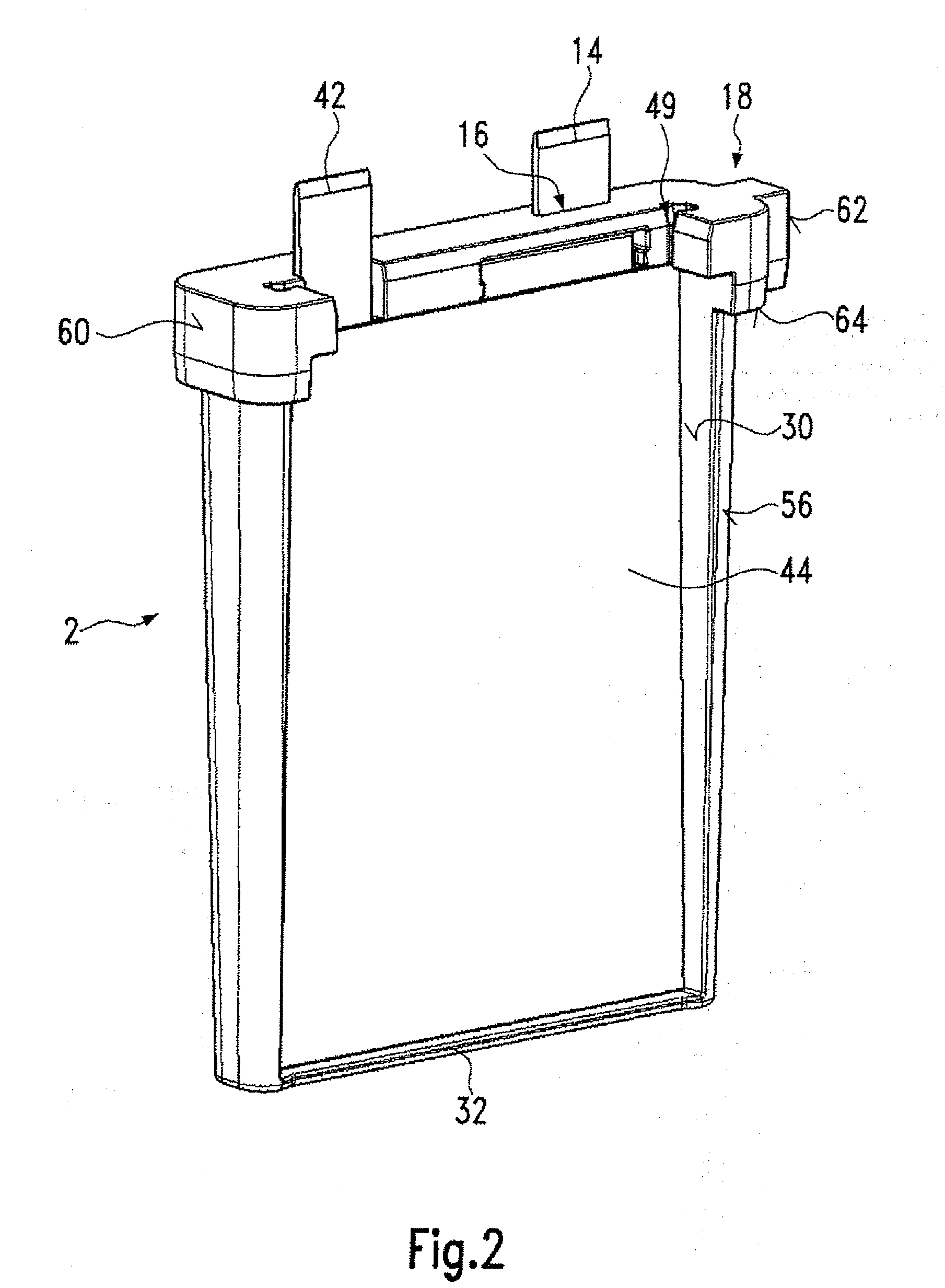
[0012]In a preferred development, the structural unit comprises the at least one PTC heating element and the two strip conductors. As already mentioned, the housing can consist of at least two housing parts that can be moved with respect to each other but that are not necessarily solidly connected to one another in the frame of the structural unit. In this way, the frame opening can also be partly formed by means of walls of one housing part and partially by walls of another housing part. Solely for reasons of assembly, it is advisable to provide a frame opening on one housing part, whereby this frame opening can hold the PTC heating element or elements within the frame sufficiently securely during the assembly. Furthermore, the strip conductor or conductors can be movable within the housing or individual housing parts, particularly in the direction towards and away from the at least one PTC heating element, in order to introduce with as little hindrance as possible an external contact force via the wedge element and into the layer composition comprising the at least one PTC heating element and the strip conductors lying on it. To reduce the number of parts and with a view to simple assembly, however, it is preferable to arrange only one strip conductor so that it can move within the limits inside the housing and to arrange the other strip conductor in such a way that it is fixed in place with respect to the housing.
[0039]The plate already mentioned in the preceding and arranged between the wedge element and the at least one PTC heating element serves to compensate the manufacturing tolerances in the method according to the invention, so that, with the method according to the invention, ceramic PTC heating elements that can have various thicknesses in an identical batch due to the manufacture can be economically used for manufacturing an electric heating device by means of using identical frames or housings.

Problems solved by technology

Nevertheless, however, the movement of the wedge element in various directions of movement is only possible within certain limits.

Method used


Image

  • Heat-Generating Element for an Electric Heating Device and Method for the Manufacture of the Same
  • Heat-Generating Element for an Electric Heating Device and Method for the Manufacture of the Same
  • Heat-Generating Element for an Electric Heating Device and Method for the Manufacture of the Same

Examples


Embodiment Construction

[0053]The embodiment shown in FIGS. 1 to 5 is a heat-generating element 1 with a one-piece housing 2, which, in a frontal view (cf. FIG. 4) is formed with a wedge shape narrowing towards the bottom. The housing 2 forms a frame 4 which encloses a frame opening 6 in which four PTC heating elements 8 can be held in this case, whereby only three PTC heating elements 8 are shown in FIG. 3. The four PTC heating elements 8 arranged one above the other in a level are held at a distance from the wall of the frame 4 by means of pins 10, which are formed from a highly insulating material, for example a silicone bonded to the plastic of the housing 2 by means of injection molding the material of the housing 2 around the pins 10, whereby said material has better insulating characteristics against leakage currents than does the plastic material of the housing 2. The pins can also be joined to the housing 2 at their base by means of one-piece injection molding and can be covered with a highly-insu...


PUM


Abstract

A heat-generating element includes at least one PTC heating element, strip conductors lying flat on it on both sides, and a frame which forms at least one frame opening for holding the at least one PTC heating element. The frame, as a part of a housing, forms a structural unit with a wedge element having a first wedge surface that extends parallel to the strip conductor and a second wedge surface that lies exposed on the exterior side of the housing and that is aligned diagonally to the first wedge surface. For fixing the heat-generating element precisely in place in a slot in the housing, the heat-generating element has spacing surfaces positioned upstream or downstream of the at least one PTC heating element in the direction of the length of the slot. Also provided is a method of manufacturing an electric heating device.

Description

BACKGROUND OF THE INVENTION[0001]1. Field of the Invention[0002]The invention under consideration relates to a heat-generating element with at least one PTC heating element, strip conductors lying flat on it on both sides and a frame which forms at least one frame opening for holding the at least one PTC heating element.[0003]2. Description of the Related Art[0004]A heat-generating element of this type is known as a part of an auxiliary heater for a motor vehicle, for example, from EP 0 350 528. Further heat-generating elements are known, for example, from DE 32 08 802, DE 30 46 995 or DE 28 04 749.[0005]Basically, with category-defining, heat-generating elements of this type, the problem that exists is that a low transition resistance should be provided by means of good mechanical contacting between the strip conductor and the PTC element, so that a current feed to the heat-generating element is possible without substantial heating at the phase interface to the PTC element. This re...

Claims


Application Information

Patent Timeline
IPC IPC(8): H05B3/14
CPCF24H3/0405F24H3/0429F24H3/0464H05B2203/02F24H9/1827H05B3/24F24H3/082H01C7/02H05B3/06
Inventor NIEDERER, MICHAELBOHLENDER, FRANZ
Owner CATEM
Learn More