Method and apparatus for magnetically activated radio or infrared identification system

a magnetically activated radio or infrared identification technology, applied in the field of electronic security systems, can solve the problems of limited distance at which they can be read, limited lifetime, and relatively expensive readers

Active Publication Date: 2008-05-01
JOHNSON CONTROLS TYCO IP HLDG LLP
View PDF8 Cites 23 Cited by
  • Summary
  • Abstract
  • Description
  • Claims
  • Application Information

AI Technical Summary

Benefits of technology

[0009]It will be appreciated that some configurations of the present invention therefore provide a security system having a long-lasting RFID or IRID tag that can transmit a signal a substantial distance or have another device relay its signal via radio, and yet last almost as long as the shelf life of the batteries used to power it. Because the batteries last throughout the useful life of the RFID or IRID tag, the tag becomes disposable at the end of life and there is no need to change batteries. Moreover, instead of having multiple readers for RFID tags, a single receiving station (or a small number of receiving stations) can be used, and active disarming stations can be replaced with completely passive disarming stations that each comprise a permanent magnet. As an alternative to replacement, existing disarming stations can be retrofitted with magnets.

Problems solved by technology

Passive RFID tags are relatively inexpensive, but the distance at which they can be read is limited, and relatively expensive readers are required.
However, all these advantages accrue at the expense of the RFID tag having a lifetime limited by the lifetime of the internal power source, which is always being drained by the transmitter.
Some alarm systems suitable for installation in a dwelling or a light commercial building use relatively inexpensive passive RFID tags, but, as a result, require many relatively expensive active readers.
These readers are already relatively expensive and processor intensive, and the readers drain a considerable amount of current.

Method used


Image

  • Method and apparatus for magnetically activated radio or infrared identification system
  • Method and apparatus for magnetically activated radio or infrared identification system
  • Method and apparatus for magnetically activated radio or infrared identification system

Examples


Embodiment Construction

[0016]As used herein, an element or step recited in the singular and proceeded with the word “a” or “an” should be understood as not excluding plural said elements or steps, unless such exclusion is explicitly stated. Furthermore, references to “one embodiment” of the present invention are not intended to be interpreted as excluding the existence of additional embodiments that also incorporate the recited features. Moreover, unless explicitly stated to the contrary, embodiments “comprising” or “having” an element or a plurality of elements having a particular property may include additional such elements not having that property.

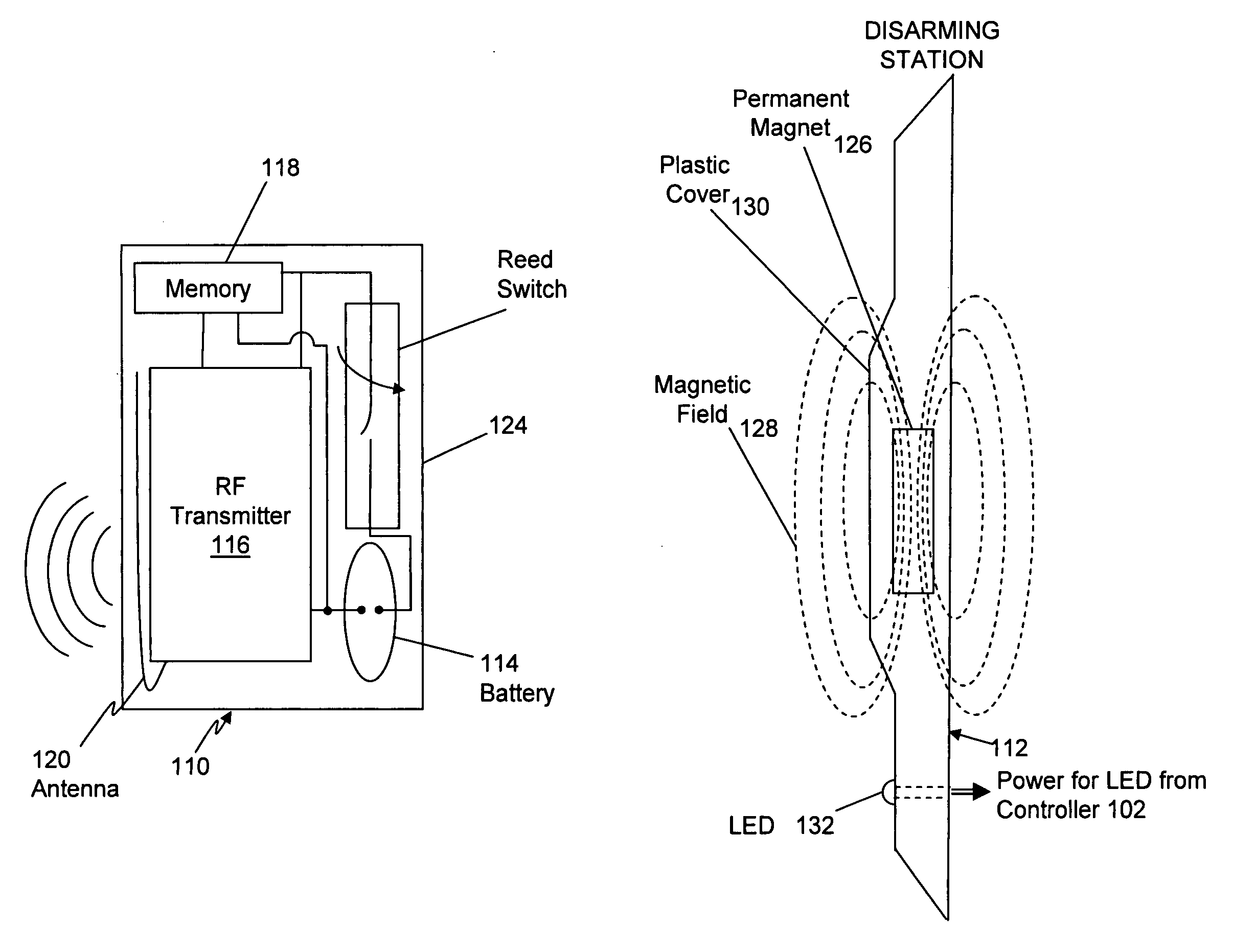
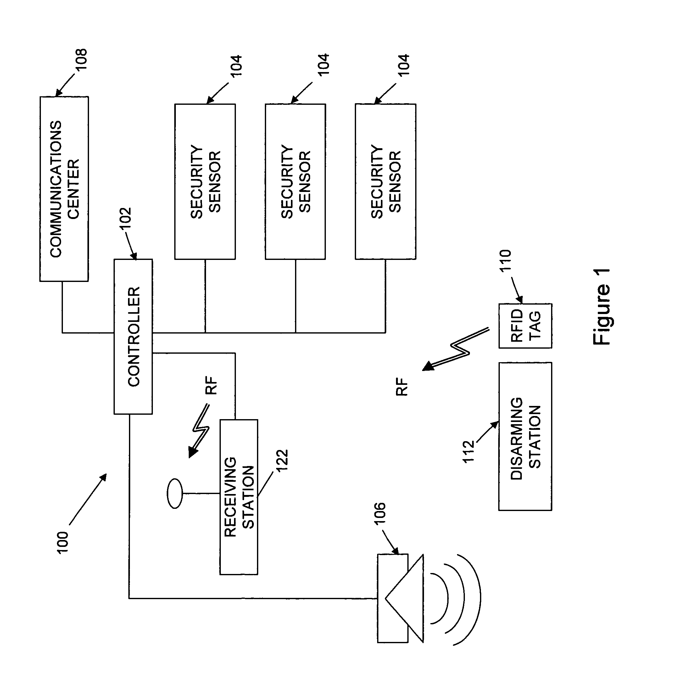
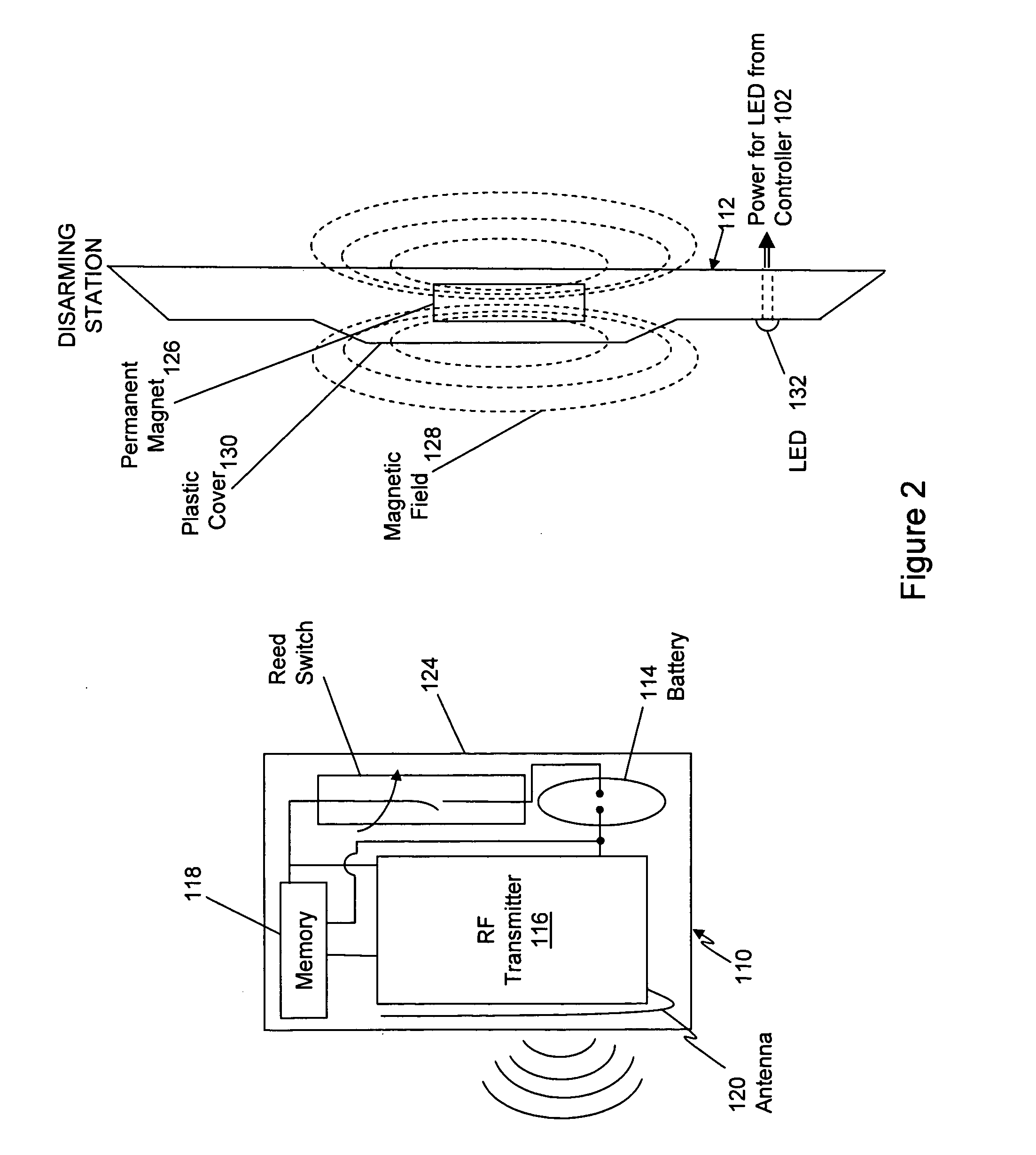
[0017]In some configurations of the present invention and referring to FIG. 1, a security system 100 may include a controller 102 and one or more security sensors 104. Security sensors 104 may include devices that detect contact breaks (e.g., sensors that detect door or window openings), glass breakage sensors, motion sensors, etc. Security sensors 104 commu...


PUM


Abstract

A disarming system for an RFID tag or an IRID tag having a magnetically operated sensor or switch includes a permanent magnet, wherein the permanent magnet is configured to activate the magnetically operated switch or sensor in the RFID tag or IRID tag when the RFID tag or IRID tag is brought into proximity of the permanent magnet. The disarming station also includes a receiving station configured to disarm a security system when the magnetically operated switch or sensor in the RFID tag or IRID tag is activated

Description

BACKGROUND OF THE INVENTION[0001]This invention relates generally to electronic security systems, and more particularly, to methods and apparatus for implementing a security system having radio frequency identification (RFID) tags or infrared identification (IRID) tags, wherein the RFID or IRID tags have long life and low cost.[0002]RFID tags are available in two basic versions, namely, “active” and “passive.” Passive RFID tags have no internal power supply. Instead, an incoming radio signal is provided just enough power to activate a CMOS integrated circuit (IC) in the tag. When activated, an outbound backscatter signal is transmitted back to the reader. This transmitted response can include an ID number or code, as well as other data. Passive RFID tags are relatively inexpensive, but the distance at which they can be read is limited, and relatively expensive readers are required.[0003]On the other hand, active RFID tags use their own internal power source to power ICs and to trans...

Claims


Application Information

Patent Timeline
Patent Type & Authority Applications(United States)
IPC IPC(8): G08B13/14
CPCG08B13/2417H03K17/9517H01H36/0006G08B25/008
Inventor SHARMA, RAMAN KUMAR
Owner JOHNSON CONTROLS TYCO IP HLDG LLP
Why Eureka
Try Eureka