See-through periscope for sighting-in optical or open sights on a firearm

Inactive Publication Date: 2008-05-08
MAYERLE RONALD T
View PDF19 Cites 21 Cited by
  • Summary
  • Abstract
  • Description
  • Claims
  • Application Information

AI Technical Summary

Benefits of technology

[0028]Practice shows that sight-to-sight co-alignment using riflescopes with see-through mounts or non-magnifying optical sights and open sights is one of the best means for sighting-in optical sights and for checking that the aimpoint is maintained. Unfortunately, see-through mounts elevate riflescopes significantly—which causes the numerous problems, and sight-to-sight co-alignment with most non-magnifying optical sights is possible only with elevated open sights, which are uncommon except on some military rifles. This invention remedies both situations by enabling sight-to-sight co-alignment with both magnifying or non-magnifying optical sights by mounting a see-through periscope upright in the gap between the front of an optical sight and a rear open sight (of the notch type or any of its variations) of normal height. Four unique mounts hold the periscope. Each mount positions the bottom mirror of the per

Problems solved by technology

Unfortunately, see-through mounts elevate riflescopes significantly—which causes the numerous problems, and sight-to-sight co-alignment

Method used


Image

  • See-through periscope for sighting-in optical or open sights on a firearm
  • See-through periscope for sighting-in optical or open sights on a firearm
  • See-through periscope for sighting-in optical or open sights on a firearm

Examples


Example

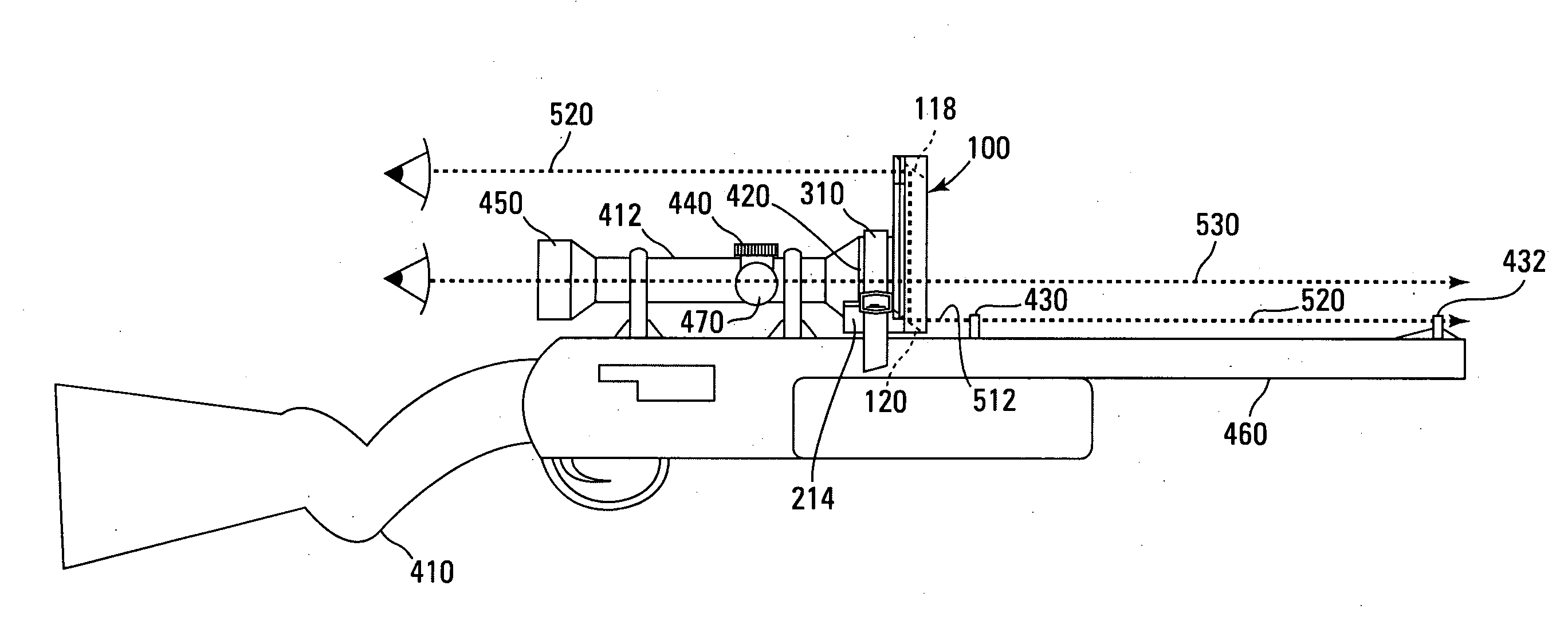
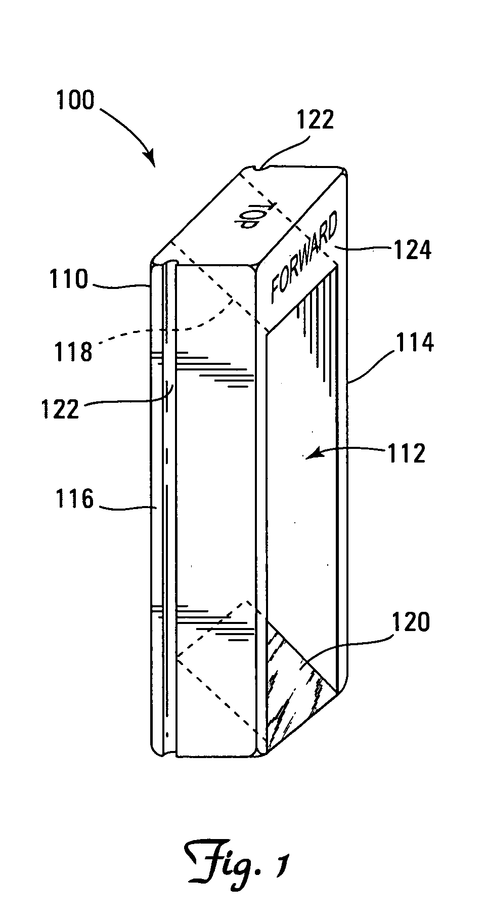
[0049]With reference to FIG. 1, a see-through periscope 100 allows shooters to align the aimpoint of one sighting system, such as an optical sight, of which examples are riflescopes, holographic and reflex sights, to the aimpoint of another sighting system, such as open sights fitted on many rifles or other firearms, of which examples include shotguns, air rifles, and muzzle loaders. Different mounts for the periscope 100, of which four are presented herein, may be required to accommodate optical sights of a wide range of types, shapes, and sizes along with open sights of different heights.

[0050]Periscope 100 comprises a generally rectangular frame 110 into which a top mirror 118 and a bottom mirror 120 are mounted. Preferably periscope 100 has no front or back panels thereby creating a window 112 about 3 inches long between the top and bottom mirrors 118, 120 and ¾ inch wide between the two side panels 114, 116 of the periscope. The frame 110 of the periscope 100 may be made from p...


PUM


Abstract

A see-through periscope for sighting-in optical sights or open sights by co-aligning one type of sighting system with the other type. The small see-through periscope is preferably used with firearms that have two conditions: (1) the rifle must be equipped with open sights, and (2) a gap must exist between the front of the optical sight and the rear open sight where the periscope can be mounted. Four unique mounts allow the periscope to be used with both magnifying or non-magnifying optical sights of different types, sizes, and shapes and open sights of different heights. The mounts position the bottom mirror at the height of the open sights and the top mirror at a point higher than the optical sight. The bottom mirror captures an image of the open sights aimed at a target and reflects that image to the top mirror, which in turn reflects the image across the top of the optical sight and into the eye of the shooter. The optical sight can still be used because the periscope mounted in front of it has no front or back panels, leaving a window for the shooter to see through the optical sight.

Description

FIELD OF THE INVENTION[0001]This invention relates generally to the field of accurate sighting of a rifle or other firearm, and more specifically relates to an apparatus and method to sight in firearms by co-aligning the aimpoint of a first sighting system with the aimpoint of another sighting system and ensuring correct aimpoints.BACKGROUND OF THE INVENTION[0002]A large number of rifles, shotguns, muzzleloaders, military firearms, etc. were and are manufactured equipped only with open sights, also called iron sights. These rifles may be subsequently fitted with optical sights such as riflescopes, reflex, and holographic sights, but in order to be accurate, these optical sights must “zeroed in.” A bullet fired from a rifle or other firearm that is zeroed in will strike a target at the aimpoint at a specific distance, given a good shooter and good shooting conditions. The process of zeroing a firearm is most commonly referred to as sighting-in. Unfortunately, current methods for sigh...

Claims


Application Information

Patent Timeline
IPC IPC(8): F41G1/40
CPCF41G1/41F41G1/40
Inventor MAYERLE, RONALD T.
Owner MAYERLE RONALD T
Why Eureka
Try Eureka