Axial rotary eddy current brake with self-adjustable braking force

a rotary eddy current brake and self-adjusting technology, applied in the direction of asynchronous induction clutch/brake, mechanical equipment, vibration suppression adjustment, etc., can solve the problems of high cost, easy failure, complex mechanism typ

Inactive Publication Date: 2008-05-08
MAGNETAR TECH
View PDF2 Cites 54 Cited by
  • Summary
  • Abstract
  • Description
  • Claims
  • Application Information

AI Technical Summary

Benefits of technology

[0003]Other rotary eddy current brakes in the field are for the most part electromagnetic devices that generally have no resistance controlling mechanism. When a control system is utilized it is usually some version of voltage control to change the strength of the magnetic field via the coils. This type of mechanism becomes complex, costly and is susceptible to failure.
[0004]The present invention capitalizes on, (among other operating parameters), the unique changes in magnetic field strength and braking force resulting from changes in speed, distance between magnets and disk(s), and magnet positional relationships, to provide a “sensing logic” and a self produced “actuating force” to change the braking force of the invention in response to changes in a particular operating parameter.
[0005]In order to solve the problems of non-uniform torque with changing speed, the main object of the present invention is to provide a brake device that can automatically provide a variable or constant torque through a range of rotational speeds without an electrical control apparatus.
[0006]The present invention lends itself to various embodiments of automatic torque adjustability which will be presented below. This automatic, self powered, adjustability represents a feature heretofore unavailable in previous rotary brakes or couplers.
[0007]An axial rotary eddy current brake in accordance with the present invention which provides for self-adjustable braking force generally includes two spaced apart support structures defining a gap therebetween with at least two permanent magnets opposingly disposed in the gap and supported by the support structure in a spaced apart relationship.
[0008]A diamagnetic disk is provided and disposed for rotation between the magnets with rotation of the disk causing eddy current braking force between the magnets and the disk and a biasing means, such as, for example, a spring, is provided for moving at least one of the magnets as a function of disk rotational speed in order to control the braking force.

Problems solved by technology

This type of mechanism becomes complex, costly and is susceptible to failure.

Method used


Image

  • Axial rotary eddy current brake with self-adjustable braking force
  • Axial rotary eddy current brake with self-adjustable braking force
  • Axial rotary eddy current brake with self-adjustable braking force

Examples


Embodiment Construction

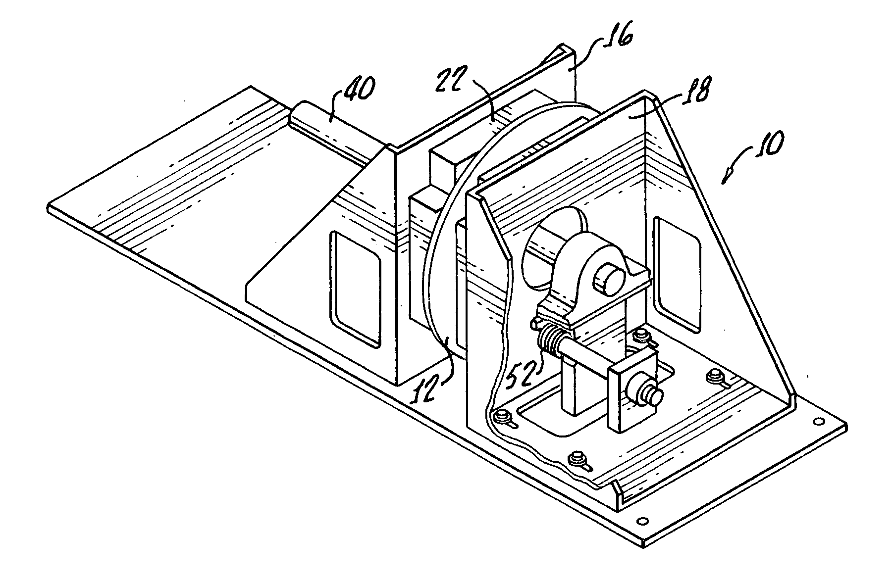
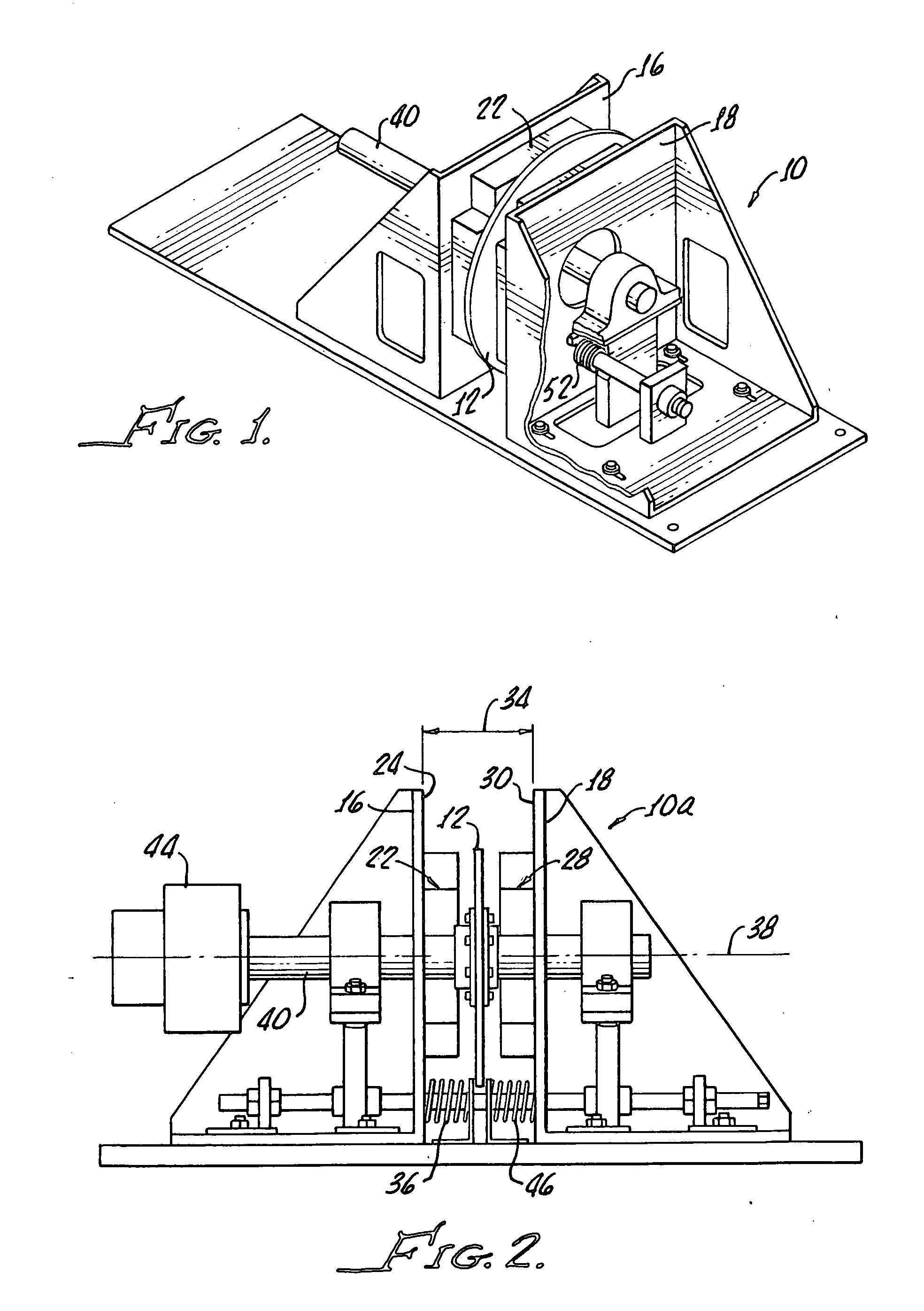
[0025]The present invention relates to an axial, automatic, self adjustable, rotary brake device using eddy current resistance, having an annular rotating conductive reaction disk fastened on a central axle, having a frame, and fitted with permanent magnets disposed on either side of said disk, wherein the magnets produce a magnetic field through the disk. Relative motion between the disk and magnets, produces eddy current resistance opposing the movement of the disk. The magnets may be mounted such that their respective positions relative to each other and thus to the intermediate conductive disk can be changed by an adjusting force, generated by the braking force, (drag), of the device itself, to increase or decrease the space between magnets and disk, (air gap) without the necessity of powered actuators or control systems.

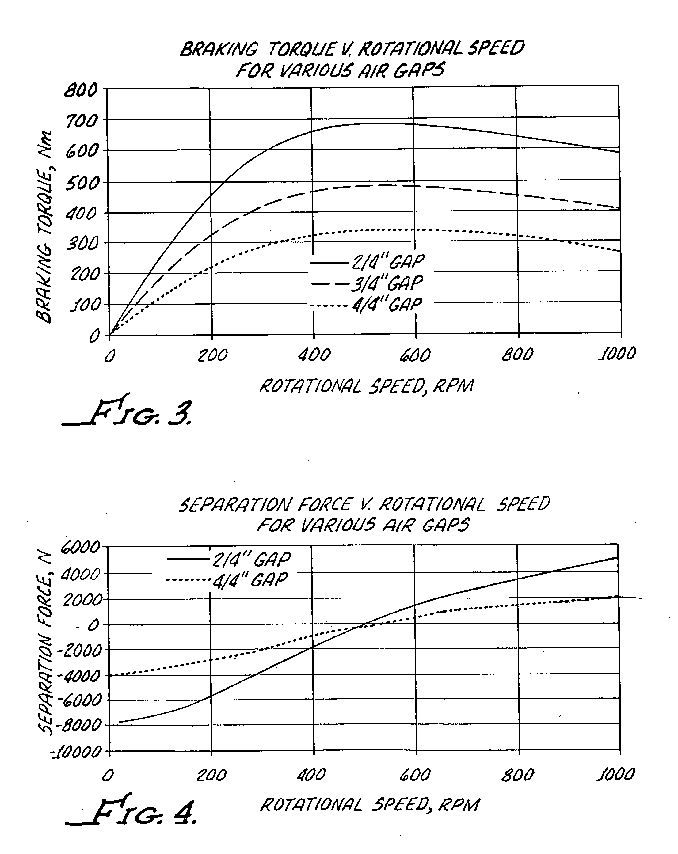
[0026]The present invention can also be so configured to provide a reduced torque output until a specific, greater predetermined rotational speed is achieved, a...


PUM


Abstract

An axial rotary eddy current brake with self adjustable braking force includes two spaced apart support structures defining a gap therebetween, at least two permanent magnets opposingly disposed in said gap and supported by the support structure in a spaced apart relationship and a diamagnetic disk disposed for rotation between the magnets, rotation of the disk causing an eddy current braking force between the magnets and the disk. Biasing apparatus is provided for moving at least one of the magnets as a function of disk rotational speed in order to control the braking force.

Description

[0001]This present invention relates to industrial equipment such as drive systems, conveyors, lifting hoists, paper rollers, metal strip rolling mills, moving equipment, vehicles wind mills and the like and more particularly to an eddy current brake for providing a constant or variable torque for controlling the mentioned equipment. This invention also relates to any type of equipment wherein linear or other directional motions can be translated into rotary motion, (as through chains, pulleys, linkage mechanisms, slides and the like), and the subject invention can subsequently be utilized as a brake, speed control, clutch, governor or other similar apparatus.[0002]Rotary mechanical friction brakes have been employed in many industrial applications, such as brakes, clutches, power transmission, or damping systems. The main advantage of the present invention, with respect to traditional mechanical friction brakes, clutches, retarding devices or tensioners, is represented by the absen...

Claims


Application Information

Patent Timeline
Patent Type & Authority Applications(United States)
IPC IPC(8): H02K49/04
CPCH02K49/046
Inventor PRIBONIC, EDWARD M.
Owner MAGNETAR TECH
Why Eureka
Try Eureka