Tiltable Mounting Bracket

a mounting bracket and tilting technology, applied in the field of tilting mounting brackets, can solve the problems of increasing the torque of the mounting bracket, increasing the complexity of the articulation, and causing considerable stress

Inactive Publication Date: 2008-05-08
PREMIER MOUNTS +1
View PDF9 Cites 23 Cited by
  • Summary
  • Abstract
  • Description
  • Claims
  • Application Information

AI Technical Summary

Problems solved by technology

As displays become heavier and/or larger they exert greater torque on the mounting bracket.
This makes articulation more complex an

Method used


Image

  • Tiltable Mounting Bracket
  • Tiltable Mounting Bracket
  • Tiltable Mounting Bracket

Examples


Embodiment Construction

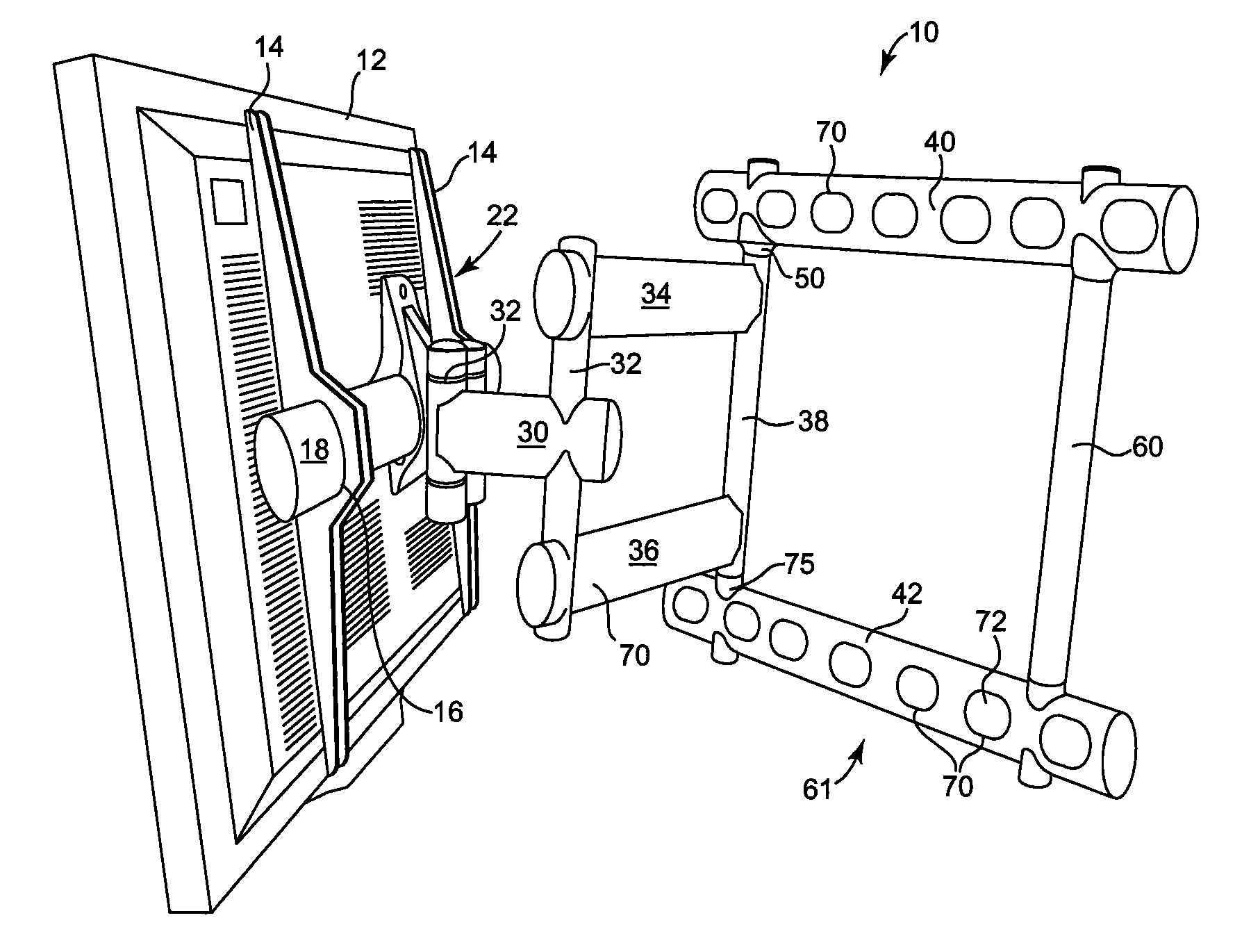
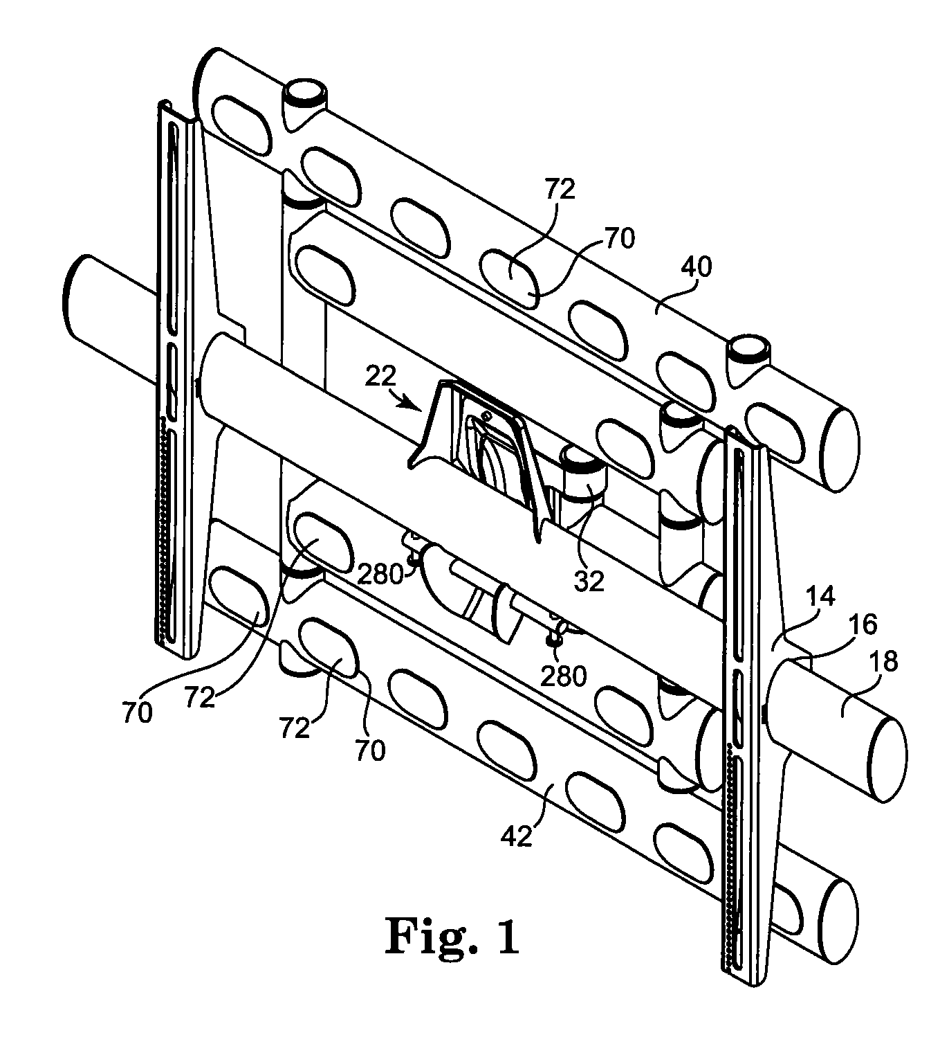
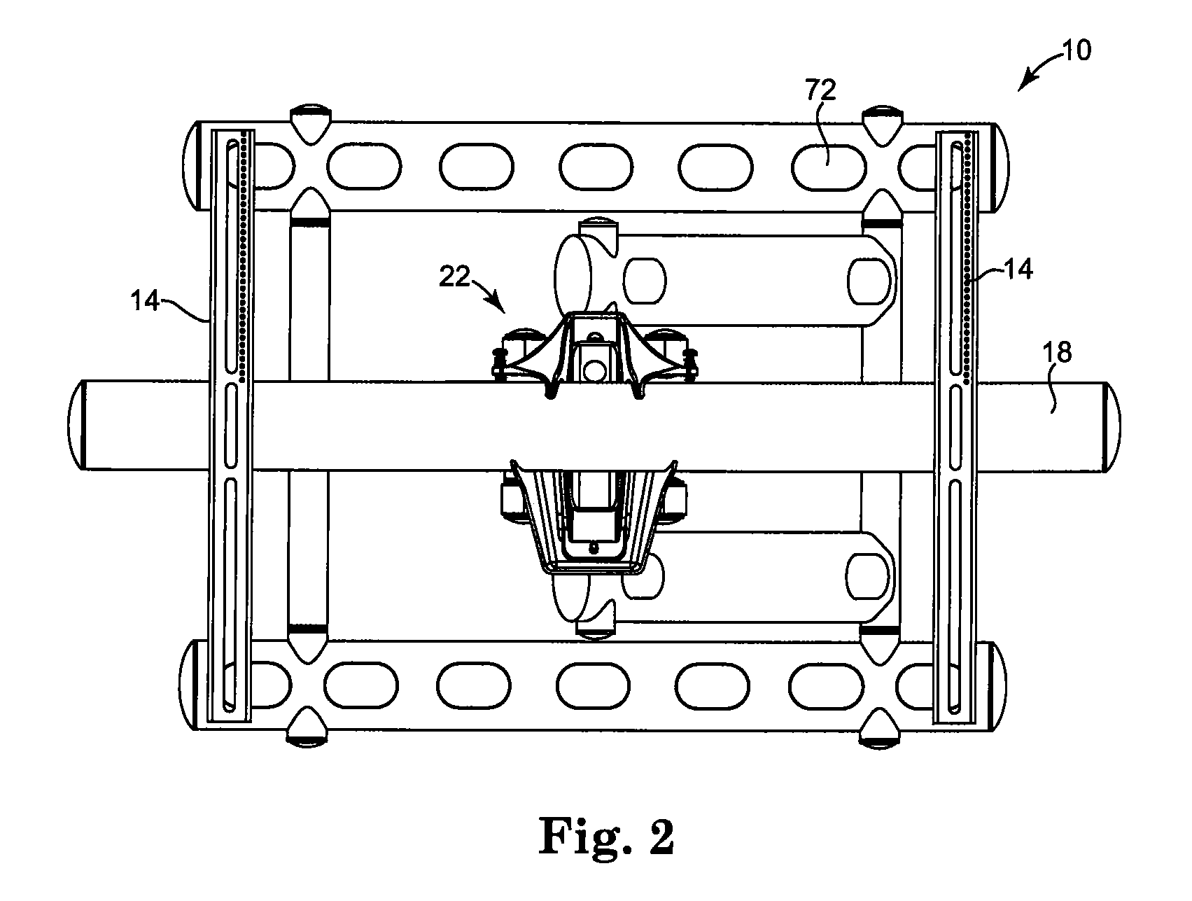
[0021]A tiltable mounting bracket system 10 is shown most clearly in FIGS. 1-3 and in an environmental view showing a display in FIG. 15.

[0022]Display 12 is an exemplary flat panel display which is affixed to the bracket system 10 by a plurality in this case, two universal brackets 14 which are in turn carried by universal bracket bar 18. In this case, the two brackets 14 are indicated although the system could be made to function with a single or more than two such brackets. The brackets are affixed to the display by means of fasteners (not shown). Brackets 14 are affixed to universal bar 18 in a number of ways. In the preferred embodiment, brackets 14 include aperture 16 which permit universal bar 18 to slide therethrough and then be affixed into place by fasteners through an aperture 20 (see FIG. 3). Universal bar 18 is shown as oval in cross section, but this is not a functional feature. It is only important that the cross section made with the aperture 16 in bracket 14 and that...


PUM


Abstract

A display bracket with tilt adjustment is disclosed which allows the installer to mount the bracket to a surface and place the display holding section in a cradle like structure without fear that it will fall. The display holding section can then be affixed to the display bracket and adjustment to the tilt angle can be made without the installer having to bear any of the display weight. Final horizontal leveling can be accomplished with set screws.

Description

CROSS-REFERENCE TO RELATED APPLICATION[0001]The present application claims the benefit of U.S. Provisional Application Ser. No. 60 / 857738 filed on 8 Nov. 2006, the complete subject matter of which is hereby incorporated herein by reference in its entirety.TECHNICAL FIELD[0002]This disclosure is directed to brackets for mounting devices to a fixed location, most commonly for mounting a flat panel display screen, or other device to a wall, with the ability to move the screen into various positions for viewing and storage.BACKGROUND OF THE INVENTION[0003]With the advent of flat panel video screens such as plasma video screens, there is a need for efficient and flexible mounting of such screens or other devices against a wall or other fixed surface. It is highly desirable to move such screens from a position adjacent a mounting surface to a position closer to the user and this may entail a mount which can articulate in many directions.[0004]As displays become heavier and / or larger they ...

Claims


Application Information

Patent Timeline
IPC IPC(8): A47F7/00
CPCF16M11/04F16M11/08F16M2200/068F16M11/2014F16M13/02F16M11/10
Inventor DOZIER, LEONARDBOUISSIERE, MICHAEL F.
Owner PREMIER MOUNTS
Why Eureka
Try Eureka