
Photographing apparatus and photographing method

a technology of photographing apparatus and photographing method, which is applied in the field of photographing apparatus, can solve the problems of reducing the brightness of the overall subject, affecting the effect of the focus control, and affecting the effect of the person's appearan

Inactive Publication Date: 2008-05-08
FUJIFILM CORP
View PDF8 Cites 63 Cited by
  • Summary
  • Abstract
  • Description
  • Claims
  • Application Information

AI Technical Summary

Benefits of technology

[0042]According to a photographing apparatus and method of the present invention, an eye is detected from image data, and the irradiation condition of the light is changed such that the light is irradiated on a position of the subject other than the detected eye, so that the light is prevented from being irradiated on the eye, and the person is prevented from feeling dazzled.
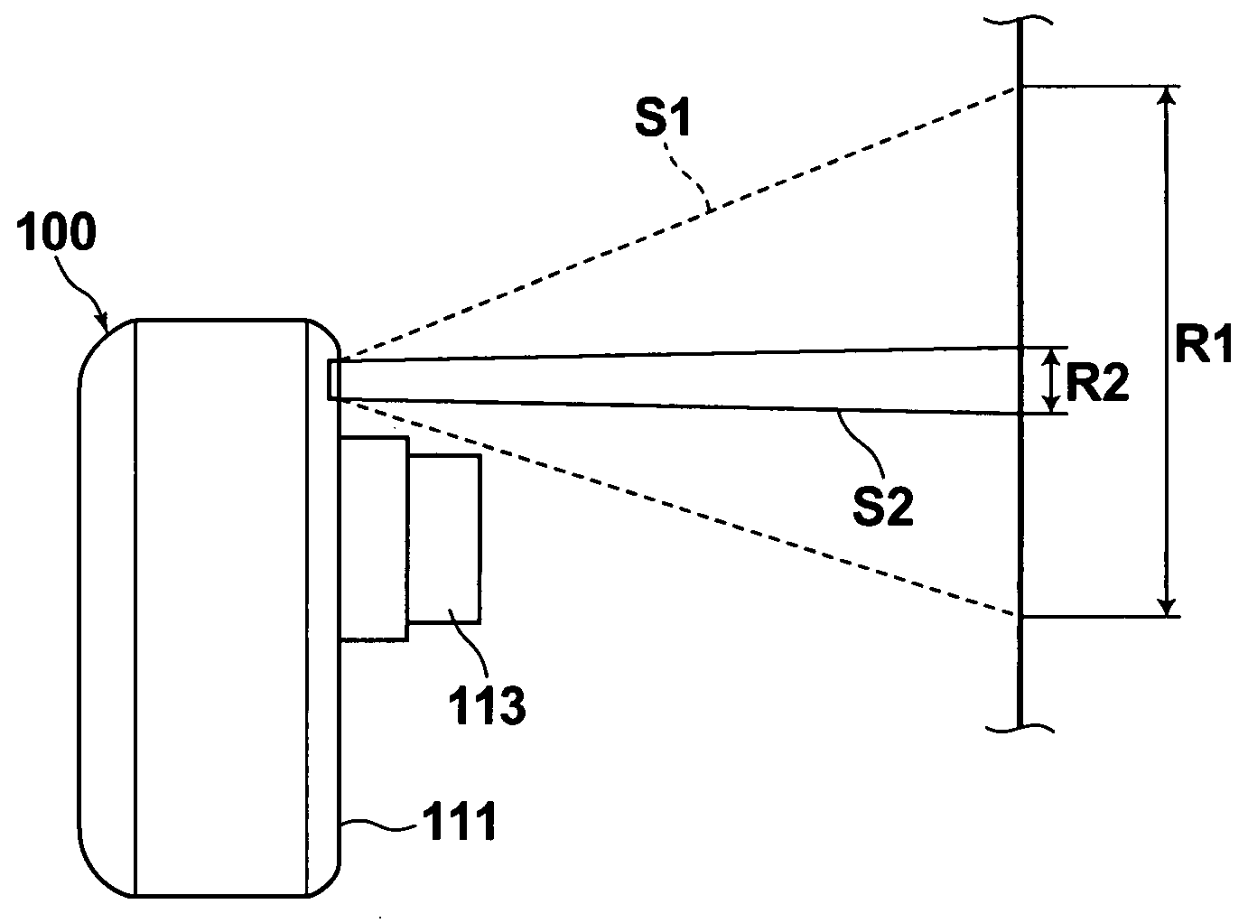
[0043]Further, according to another photographing apparatus and method, when focus control of the taking lens is performed during the nighttime or in a dark place, the position of a human or animal eye is identified, and auxiliary light is irradiated onto a position other than the identified position of the human or animal eye, so that the auxiliary light irradiated when focus control of the taking lens is performed is prevented from entering the eye of the human or animal subject. This prevents the human or animal subject from feeling dazzled.
[0044]Still further, when a human or animal face image is unable to be detected, wide-angle auxiliary light is irradiated, so that the position of a human or animal eye is invariably identified. This allows narrow-angle auxiliary light to be irradiated onto a position other than the identified position of the eye, thereby the focus control of the taking lens may be performed with respect to the human or animal within the subject image.
[0046]Still further, the identification of the position of the eye is also performed while the focus control is performed by irradiating the narrow-angle auxiliary light, so that even if the number of humans or animals is increased or if the position of the human or animal is changed in the middle of the photographing, the position of the human or animal eye may be invariably identified. This allows the narrow-angle auxiliary light to be irradiated onto a position other than the identified position of the human or animal eye, so that the focus control of the taking lens may be performed with respect to the human or animal subject.

Problems solved by technology

When focus control of the taking lens is performed based the image signals from the image sensor in the manner as described above, it is often the case that the focus control is not performed properly under photographing conditions in which the overall subject brightness is reduced, such as during the nighttime or in a dark place, since the contrast of the subject itself becomes low.
For example, when measuring the three-dimensional shape of a human face, the beam forming the reference point may be irradiated onto the eyes of the person, which poses a problem that the person is dazzled.
Further, in the case of a digital camera in which the focus control is performed using the face portion of a person or the like, the auxiliary light is naturally irradiated on the face portion, and the auxiliary light may enter into the eyes of the person so that it has a disadvantage that the person is caused to feel dazzled.

Method used


Image

  • Photographing apparatus and photographing method
  • Photographing apparatus and photographing method
  • Photographing apparatus and photographing method

Examples


first embodiment

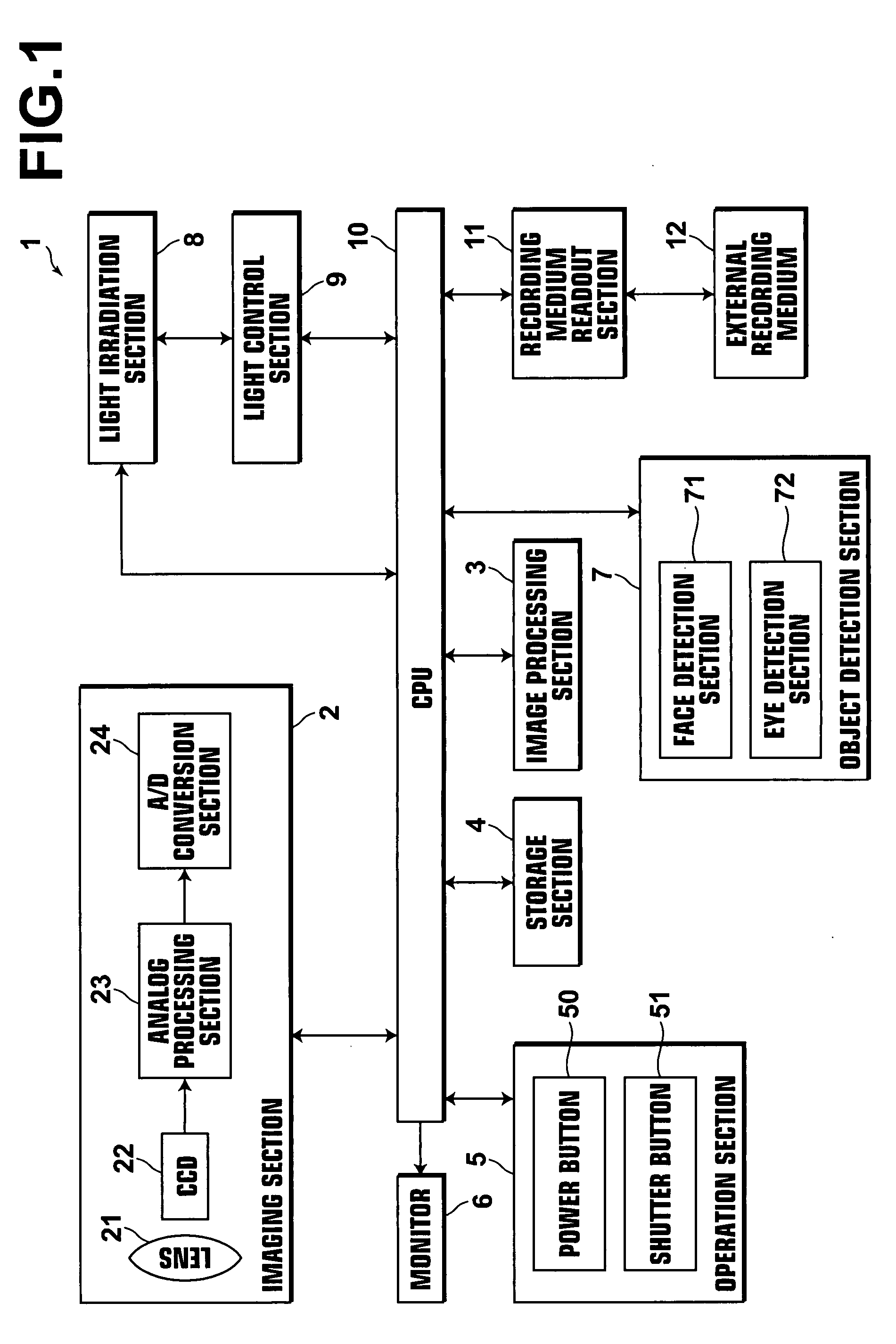
[0071]Hereinafter, the photographing apparatus according to the present invention will be described in detail with reference to the accompanying drawings. In the following embodiments, description will be made of a case in which a digital camera having light irradiation unit is described as the photographing apparatus of the present invention, but the invention is not limited to this, and the invention is applicable to other electronic devices having an electronic photographing function with light irradiation unit, such as digital video cameras, camera phones, PDAs with a built-in camera, and the like. FIG. 1 is a block diagram of the digital camera 1 according to the present embodiment, schematically illustrating the structure thereof.

[0072]The digital camera 1 of the present embodiment includes a CPU 10, an imaging section (imaging unit) 2, an image processing section 3, a storage section 4, an operation section 5, a liquid crystal monitor (display unit) 6, an object detection sec...

second embodiment

[0144]Next, a digital camera 100, as the photographing apparatus according to the present invention, will be described in detail with reference to the accompanying drawings.

[0145]As illustrated in FIGS. 13 and 14, the digital camera 100 includes a retractable lens camera cone 113 including a taking lens 112 on the front face of the camera body 111. The lens camera cone 113 protrudes to the position shown in FIG. 13 when used, and received within the camera body 111 when not used. Further, a flash emission section 115, a finder objective window, and an auxiliary light window 117 are provided on the front face of the camera body. The auxiliary light window 117 is provided for irradiating AF auxiliary light from an auxiliary light irradiation unit 140 provided inside of the camera body 111 onto a subject when performing focus control of the taking lens 112 under dark ambient conditions, such as during the nighttime.

[0146]A finder ocular window 121, a liquid crystal display (LCD) 122, a...


PUM


Abstract

A photographing apparatus including: an imaging unit for obtaining image data by imaging a subject; a light irradiation unit for irradiating light onto the subject when photographing; an eye detection unit for detecting a human or animal eye; and a light control unit for changing the irradiation condition of the light such that the light is irradiated on a position of the subject other than the eye detected by the eye detection unit.

Description

BACKGROUND OF THE INVENTION[0001]1. Field of the Invention[0002]The present invention relates to a photographing apparatus, such as a digital camera, and, in particular, to a photographing apparatus and method in which light is irradiated onto a subject.[0003]2. Description of the Related Art[0004]Recently, various methods for measuring a three-dimensional shape of a predetermined object using a photographing apparatus, such as a digital camera, have been proposed. One of the methods is a stereo matching method in which a predetermined object is imaged from different directions using a plurality or a single photographing apparatus to obtain a plurality of sets of image data, then a commonly imaged point in each set of image data (reference point) is identified, and distances to the reference point are measured according to the triangulation principle to estimate the three-dimensional shape of the predetermined object. The methods for identifying the reference point include a method ...

Claims


Application Information

Patent Timeline
Patent Type & Authority Applications(United States)
IPC IPC(8): H04N5/225
CPCH04N5/2256H04N5/23219H04N5/232H04N23/56H04N23/611
Inventor NAKAO, SOICHIROUENO, TOSHIHARUNAKANISHI, TAKAO
Owner FUJIFILM CORP
Learn More