
Jet pump diffuser weld repair device and method

a technology of diffuser and repair device, which is applied in auxillary welding devices, greenhouse gas reduction, nuclear elements, etc., can solve the problems of loss of total jet pump assembly, failure of jet pump functionality in providing recirculation flow path to reactor core, loss of 23-core height coverage,

Inactive Publication Date: 2008-05-08
GENERAL ELECTRIC CO
View PDF14 Cites 37 Cited by
  • Summary
  • Abstract
  • Description
  • Claims
  • Application Information

AI Technical Summary

Benefits of technology

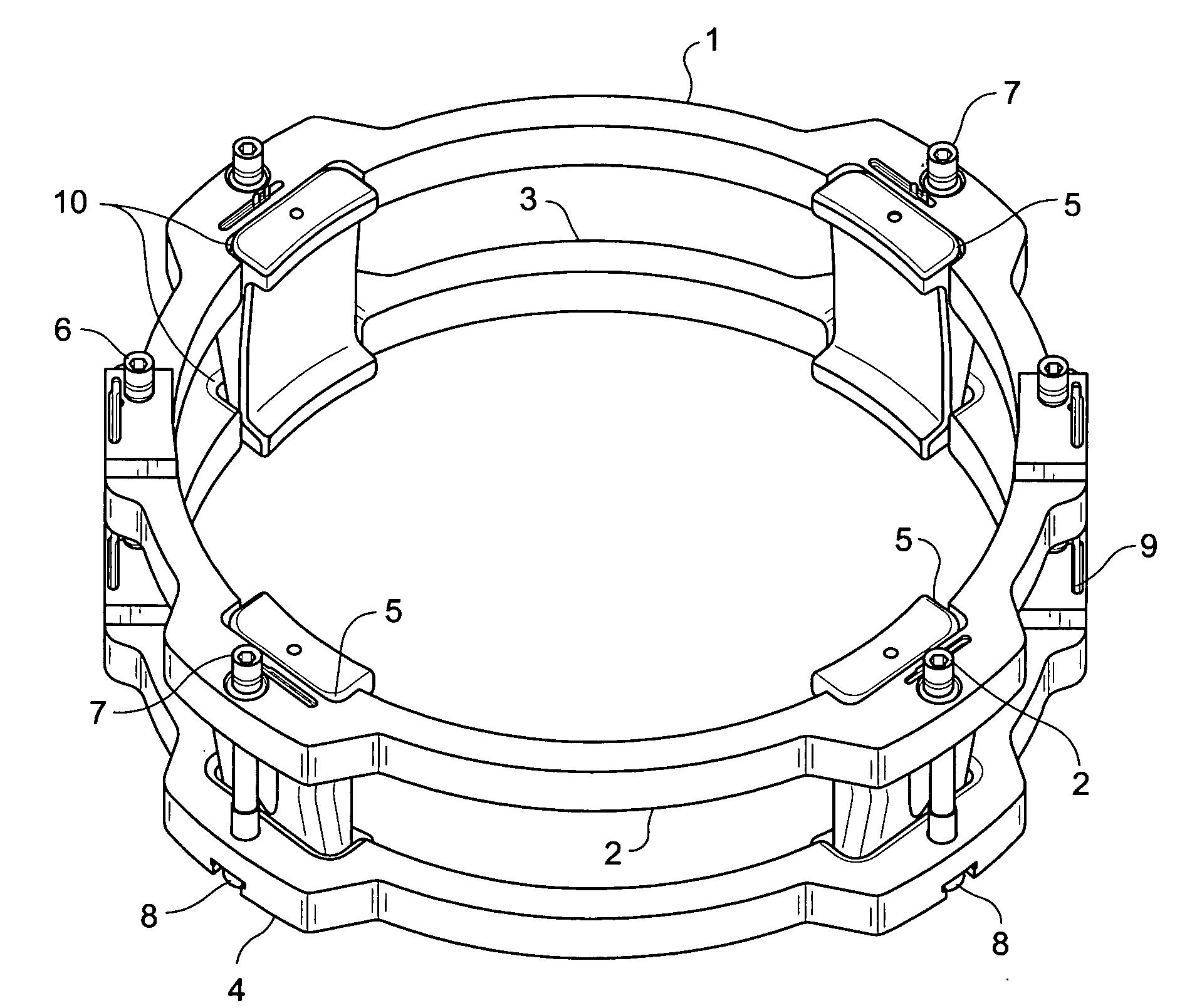
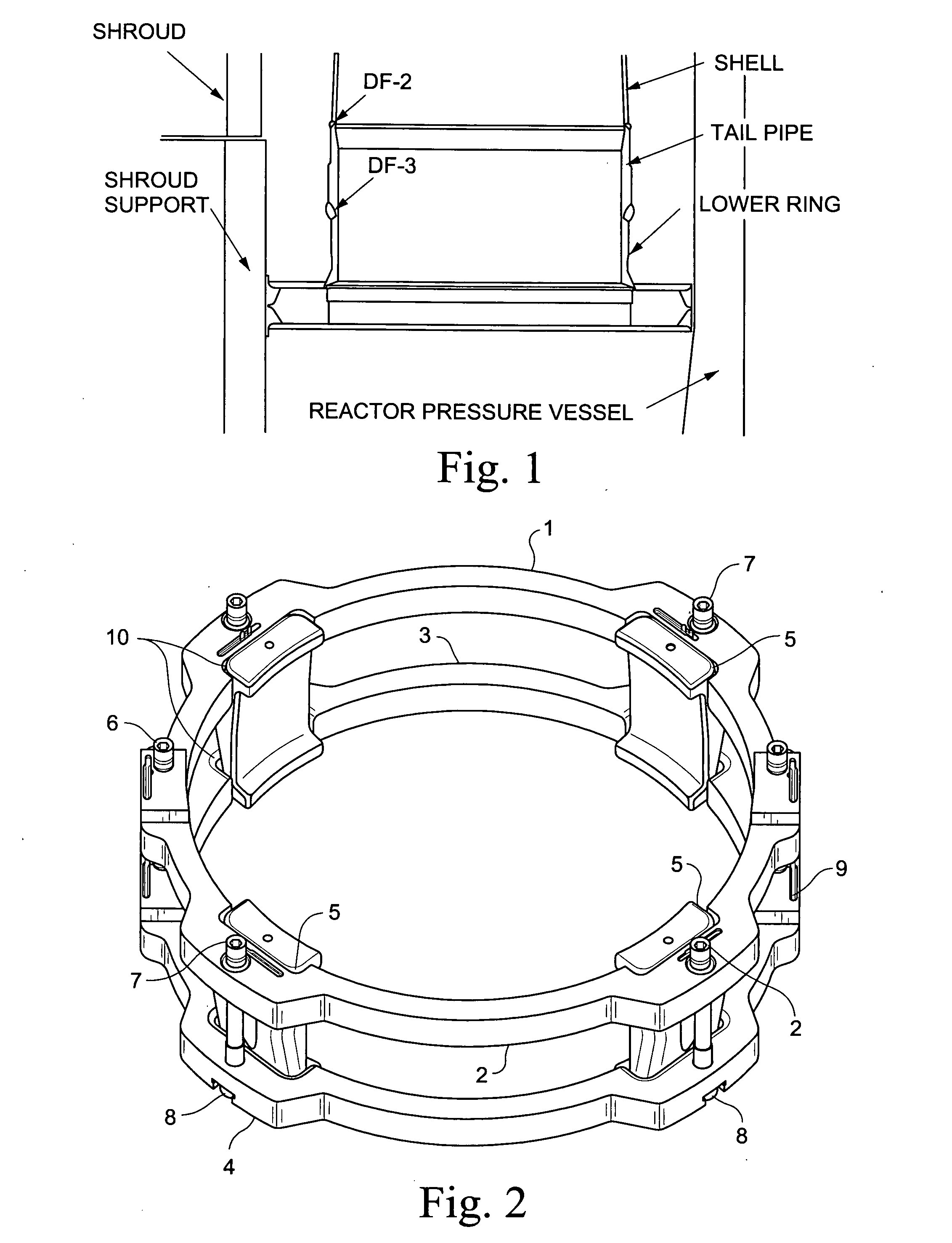
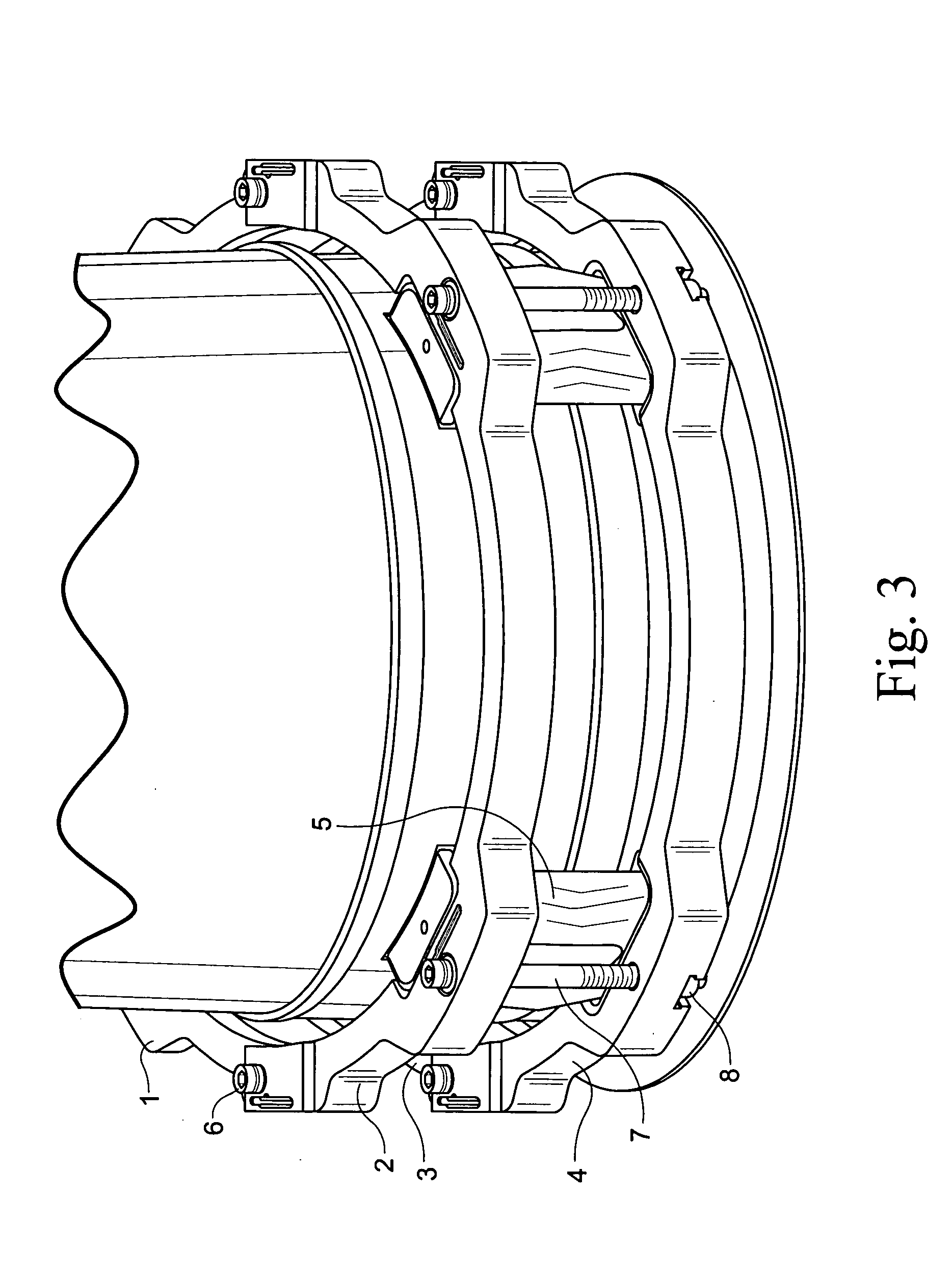
[0007]In an exemplary embodiment of the invention, a jet pump diffuser weld repair device includes a lower ring section and an upper ring section respectively sized to fit around a circumference of the diffuser on opposite sides of the weld to be repaired. The lower and upper ring sections are provided with a plurality of aligned gripper slots. A corresponding plurality of grippers are fit into the gripper slots, where at least one of the gripper slots and the grippers defines cam surfaces shaped to drive the grippers radially inward as the lower and upper ring sections are drawn toward each other. A plurality of connector bolts are secured between the lower ring section and the upper ring section. Tightening the

Problems solved by technology

The postulated crack in a DF-3 or a DF-2 weld would detach the diffuser from the jet pump assembly, resulting in the total loss of the jet pump assembly.
This could in turn result in failure of jet pump functionality in providing recirculation flow path to reactor core and loss of providing the ⅔-core height coverage in the event of LOCA accident.
Jet pump diffuser weld cracks that have required repair have been a relatively recent occurrence.
The scope of that repair was limited to hardware design and analysis and installation tooling concept design.

Method used


Image

  • Jet pump diffuser weld repair device and method
  • Jet pump diffuser weld repair device and method
  • Jet pump diffuser weld repair device and method

Examples


Embodiment Construction

[0017]The jet pump diffuser repair described herein structurally replaces any one of the DF-3 or DF-2 welds. This will provide for the required vertical and lateral support of the diffuser assembly, even if complete failure of one of these welds occurs. The design of the repair assumes that other welds in the diffuser assembly remain intact (welds connecting collar / shell / tail pipe) and other components of the jet pump assembly as well. Thus, it is preferably that the installation of only one jet pump diffuser repair is permitted on any jet pump pair. The estimated design life of the diffuser repair clamp is 40 years.

[0018]With reference to FIG. 2, a lower ring section includes a clamp half lower female 3 and a clamp half lower male 4 bolted together using two connector bolts 6. The upper ring section includes a clamp half upper female 1 and a clamp half upper male 2 bolted together using two connector bolts 6. The female clamp half connections contain T-slots 14 or other suitable st...


PUM

PropertyMeasurementUnit
Thicknessaaaaaaaaaa
Shapeaaaaaaaaaa
Circumferenceaaaaaaaaaa

Abstract

A jet pump diffuser weld repair device includes a lower ring section and an upper ring section respectively sized to fit around a circumference of the diffuser on opposite sides of the weld to be repaired. The lower and upper ring sections are provided with a plurality of aligned gripper slots. A corresponding plurality of grippers are fit into the gripper slots, where at least one of the gripper slots and the grippers defines cam surfaces shaped to drive the grippers radially inward as lower and upper ring sections are drawn toward each other. A plurality of connector bolts are secured between the lower ring section and the upper ring section. Tightening of the connector bolts draws the lower and upper ring sections toward each other.

Description

BACKGROUND OF THE INVENTION[0001]A remotely installable jet pump diffuser weld repair device structurally replaces cracked adapter or lower ring to tail pipe welds and the tail pipe to shell welds. The device is remotely installable in the limited space in the shroud to vessel annulus of boiling water reactor (BWR) power plants.[0002]The jet pump assembly is part of the reactor recirculation system. Each assembly includes a riser assembly, a riser brace, two inlet-mixer assemblies, and two diffuser assemblies. Each assembly is installed in the annulus between the reactor pressure vessel (RPV) and the shroud. There are twenty jet pumps (ten jet pump assemblies) installed in a typical General Electric BWR. The riser assembly is welded to the reactor pressure vessel (RPV) at the riser brace location, and the recirculation inlet nozzle at the penetration. The two diffuser assemblies are welded to the shroud support plate.[0003]The two inlet-mixer assemblies are removable components. The...

Claims


Application Information

Patent Timeline
IPC IPC(8): G21C9/00F16L25/00F16G11/04
CPCG21C17/017Y10T29/49741G21Y2004/30Y10T403/4345G21Y2004/501G21Y2002/304Y10T29/531G21Y2002/401Y10T29/49732G21Y2004/504G21C15/25Y10T29/49739Y02E30/40G21C19/207Y10T29/49744G21C19/02B23K37/0435Y02E30/30
Inventor KOEPKE, BARRY HAL
Owner GENERAL ELECTRIC CO
Learn More