
Spiculation detection method and apparatus for CAD

a detection method and apparatus technology, applied in the field of digital image processing technique, can solve the problems of difficult to distinguish malignant lesions from benign lesions, difficult to achieve reliable cancer detection, and difficult to distinguish benign lesions from malignant ones

Inactive Publication Date: 2008-05-08
FUJIFILM CORP
View PDF6 Cites 2 Cited by
  • Summary
  • Abstract
  • Description
  • Claims
  • Application Information

AI Technical Summary

Benefits of technology

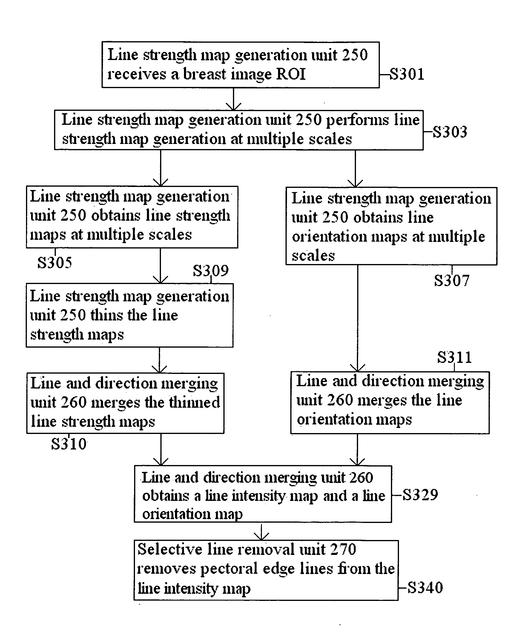
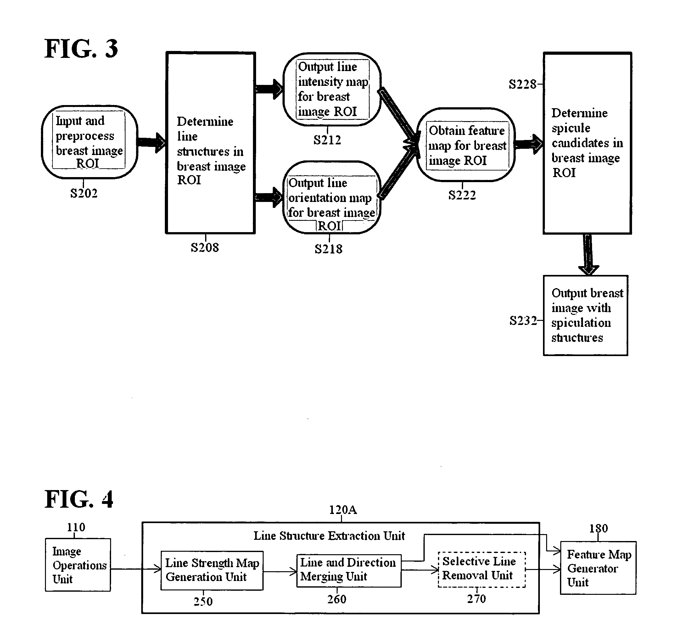
[0009]The present invention is directed to a method and an apparatus for identifying a spicule candidate in a medical image. According to a first aspect of the present invention, an image processing method for identifying a spicule candidate in a medical image comprises: accessing digital image data representing an image including a tissue region; processing the digital image data by generating at least one line orientation map and at least one line strength map for the tissue region for at least one scale, using separable filters; calculating spicule feature values based on the at least one line orientation map and the at least one line strength map; and identifying a spicule candidate based on the calculated features values.
[0010]According to a second a

Problems solved by technology

Reliable cancer detection, however, is difficult to achieve because of variations in anatomical shapes of breasts and medical imaging conditions.
Moreover, malignant lesions are often difficult to distinguish from benign lesions.
Such imaging situations pose challenges for both manual identification and computer-aided detection of cancer in breasts.
Moreover, spiculated structures indicate a much higher risk of malignancy, than calcifications and other types of structural mass changes.
Hence, spiculation detection is often difficult or ineffective if the extracted line structures are not good enough for spiculation detection.
This technique, however, still poses computational problems for automated detection of spiculated structures, because of the large computational load required by the technique.
Moreover, the statistical analysis used to detect spiculated structures in this technique does not characterize well aspects of spiculated structures, such as the directional diversity of spiculated line structures.
Hence, this technique encounters challenges when used for automated detection of spiculated structures in breasts.

Method used


Image

  • Spiculation detection method and apparatus for CAD
  • Spiculation detection method and apparatus for CAD
  • Spiculation detection method and apparatus for CAD

Examples


Embodiment Construction

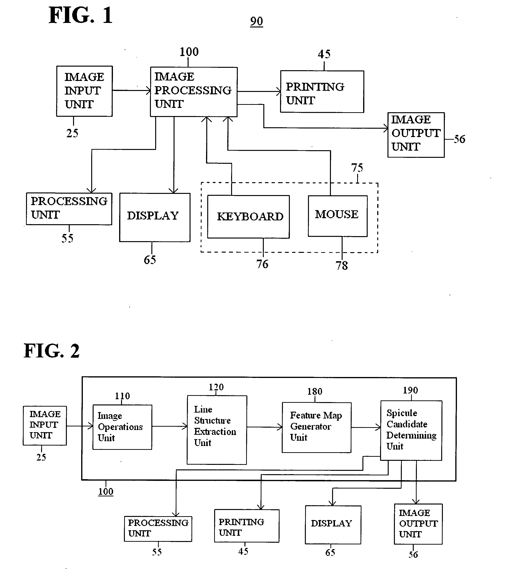
[0037]Aspects of the invention are more specifically set forth in the accompanying description with reference to the appended figures. FIG. 1 is a general block diagram of a system including an image processing unit for spiculation detection according to an embodiment of the present invention. The system 90 illustrated in FIG. 1 includes the following components: an image input unit 25; an image processing unit 100; a display 65; a processing unit 55; an image output unit 56; a user input unit 75; and a printing unit 45. Operation of the system 90 in FIG. 1 will become apparent from the following discussion.

[0038]The image input unit 25 provides digital image data representing medical images. Medical images may be mammograms, X-ray images of various parts of the body, etc. Image input unit 25 may be one or more of any number of devices providing digital image data derived from a radiological film, a diagnostic image, a digital system, etc. Such an input device may be, for example, a...


PUM


Abstract

A method and an apparatus identify a spicule candidate in a medical image. The method according to one embodiment accesses digital image data representing an image including a tissue region; processes the digital image data by generating at least one line orientation map and at least one line strength map for the tissue region for at least one scale, using separable filters; calculates spicule feature values based on the at least one line orientation map and the at least one line strength map; and identifies a spicule candidate based on the calculated features values.

Description

BACKGROUND OF THE INVENTION[0001]1. Field of the Invention[0002]The present invention relates to a digital image processing technique, and more particularly to a method and apparatus for processing medical images and detecting malignant areas in a medical image.[0003]2. Description of the Related Art[0004]Mammography images and identification of abnormal structures in mammography images are important tools for diagnosis of medical problems of breasts. For example, identification of cancer structures in mammography images is important and useful for prompt treatment and prognosis.[0005]Reliable cancer detection, however, is difficult to achieve because of variations in anatomical shapes of breasts and medical imaging conditions. Such variations include: 1) anatomical shape variations between breasts of various people or breasts of the same person; 2) lighting variations for medical images of breasts, taken at different times; 3) pose and view changes in mammograms; 4) change in anato...

Claims


Application Information

Patent Timeline
IPC IPC(8): G06K9/00
CPCG06T7/0012G06T2207/30068G06T2207/10116
Inventor OH, SEUNGSEOK
Owner FUJIFILM CORP
Learn More