
Wristband With Contoured Comfort Sides

a wristband and contour technology, applied in wristbands, identification means, protective garments, etc., can solve the problems of increasing the likelihood of sharp edges, abrasion or cuts on the left leg, etc., to reduce the risk of harm, soften the edge pressure, and increase the comfort

Active Publication Date: 2008-05-15
ZEBRA TECH CORP
View PDF99 Cites 19 Cited by
  • Summary
  • Abstract
  • Description
  • Claims
  • Application Information

AI Technical Summary

Benefits of technology

[0004]As a result of the assignee's continuing efforts to improve these wristband designs, the inventor herein has succeeded in designing an improvement which increases the comfort, and reduces the risk of harm, for not only the assignee's designs but also virtually all other flexible wristbands. In simple terms, the inventor has succeeded in developing a “bending yielding feature” for softening the edge pressure exerted by the edges of the wristband to the wearer's wrist or ankle. This bending yielding feature is especially useful for wristband designs in popular use today which are made of flexible vinyl or other thin plastic laminates. These materials are quite strong which allow them to be made from especially thin or lightweight plies, thereby increasing the likelihood that they exhibit a sharp edge which when pressed against the wrist or ankle is likely to cut or abrade it.
[0005]In simple terms, a “bending yielding feature” can be understood as any design that, inter alia, essentially adds “yieldability”, adds flex, or presents a smooth surface to a wearer's skin. In essence, a non-linear edge would seem to the inventor to satisfy this requirement. Examples of this feature include a scalloped edge design, a “toothed” edge design, a “slotted” edge design, a “folded over” edge design, and other “non-straight” edges. Some of these designs extend the length of the edge to be longer than a straight line measurement. Others of these designs provide design elements that are more flexible than a simple straight edge would provide. Still others, such as a folded over edge, provide an actual cushion at the edge which comes into contact with the wearer's wrist as the wrist is flexed or ankle as it is flexed. All are enough to help prevent a sharp edge from coming into contact with the wearer's wrist or ankle as the wrist or ankle is flexed.

Problems solved by technology

For newborns, some of whom have wristbands placed on both ankles, the wristband on the right leg could cause an abrasion or cut on the left leg as the baby thrashes about, and vice versa.
These materials are quite strong which allow them to be made from especially thin or lightweight plies, thereby increasing the likelihood that they exhibit a sharp edge which when pressed against the wrist or ankle is likely to cut or abrade it.

Method used


Image

  • Wristband With Contoured Comfort Sides
  • Wristband With Contoured Comfort Sides
  • Wristband With Contoured Comfort Sides

Examples


Embodiment Construction

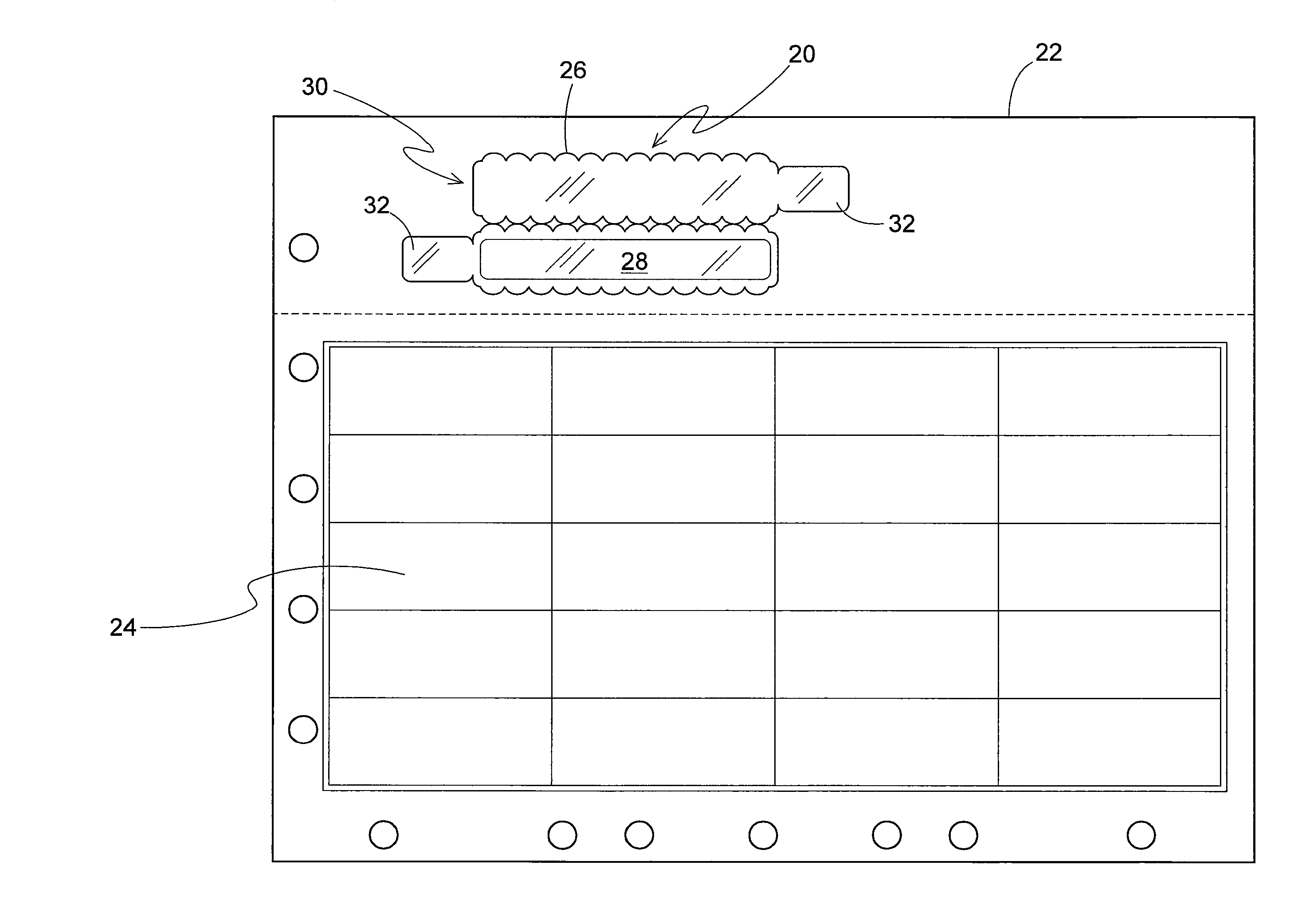
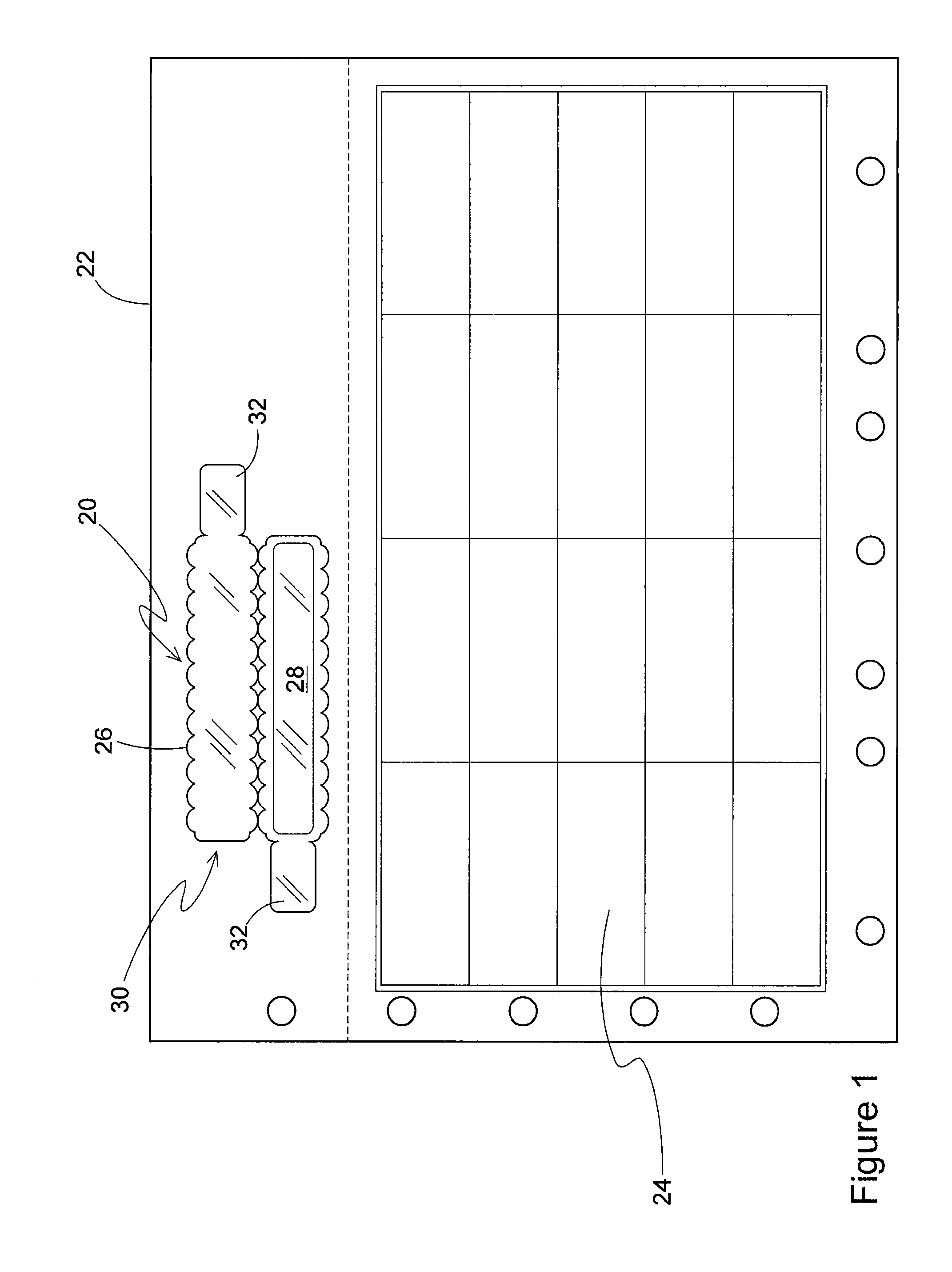
[0012]As shown in FIG. 1, the first patented wristband design 20 as included on a page sized sheet 22 along with a matrix of self adhering labels 24 may be readily adapted for application of the bending yielding feature 26 of the present invention. The wristband design 20 includes an imaging or printable face stock area 28 upon which is printed a patient's name, attending doctor's name, a bar code, etc. and then a clamshell lamination ply 30 is folded over to substantially encapsulate the face stock area 28 with a pair of integrally formed self adhering tabs 32 used for attaching the wristband to the patient. This construction is described in greater detail in several of the patents mentioned above.

[0013]The bending yielding feature 26 is shown as preferably being a scallop shaped design although any of the other designs shown in FIG. 3 could be used as well. The scallop shaped design presents a design that is visually pleasing, does not create any “loose ends” as in other designs w...


PUM


Abstract

A bending yielding feature for use along an edge of any flexible wristband design provides a cushioning effect to a wearer's wrist or ankle as the wristband is worn, thereby helping to prevent injury to the wearer's wrist or ankle as he flexes his wrist or ankle against the wristband. The bending yielding feature can include many edge designs such as a scalloped edge, a curved edge, an edge with a series of extending flaps, and other such shapes.

Description

CROSS-REFERENCE TO RELATED APPLICATIONS[0001]This application is related to two other applications being filed concurrently herewith. They are “Wristband with Snap Closure and Patient ID Label” having serial no. ______, and attorney docket no. 53248.62414; and “Laminate Web Wristband” having serial no. ______, and attorney docket no. 53248.62417; both of even filing date herewith and the disclosures of which are incorporated herein by reference.BACKGROUND AND SUMMARY OF THE INVENTION[0002]Wristbands for use in admitting and identifying patients for both in patient and out patient care are routinely used in the medical community today. The assignee hereof owns a number of patents disclosing and claiming various inventive wristband suited to this medical field application, and which have experienced great commercial success. Examples of these include U.S. Pat. Nos. 5,933,993; 6,000,160; 6,067,739; 6,438,881; 6,510,634; 6,748,687; 7,047,682; 7,017,293; and 7,017,294, the disclosures of...

Claims


Application Information

Patent Timeline
Patent Type & Authority Applications(United States)
IPC IPC(8): A41D19/00
CPCA44C5/0053G09F3/005
Inventor GREER, MARK
Owner ZEBRA TECH CORP
Learn More