Punch working apparatus and method

a working apparatus and working method technology, applied in metal working apparatus, metal-working apparatus, manufacturing tools, etc., can solve the problems of unable to form a good sheared surface and sometimes bulge the punch radially outward, and achieve the effect of good sheared surface of a produ

Inactive Publication Date: 2008-05-15
FCC KK
View PDF6 Cites 7 Cited by
  • Summary
  • Abstract
  • Description
  • Claims
  • Application Information

AI Technical Summary

Benefits of technology

[0010]Accordingly, there is a need in the art for a punch working apparatus that can avoid interference between the die and the punch and thus obtain a good sheared surface of a product.

Problems solved by technology

However, since the scraps resulted from the punch working are contained in a containing space of the punch, the punch may sometimes bulge radially outward due to internal stress of the scraps contained in the punch acting radially outwardly against the punch.
Although it may be possible to set a relatively large clearance between the die and the punch in order to solve this problem, shear drop or burring would be caused in the sheared surface and thus a good sheared surface cannot be formed.

Method used


Image

  • Punch working apparatus and method
  • Punch working apparatus and method
  • Punch working apparatus and method

Examples


Embodiment Construction

[0026]Embodiments will be hereinafter described with reference to the drawings.

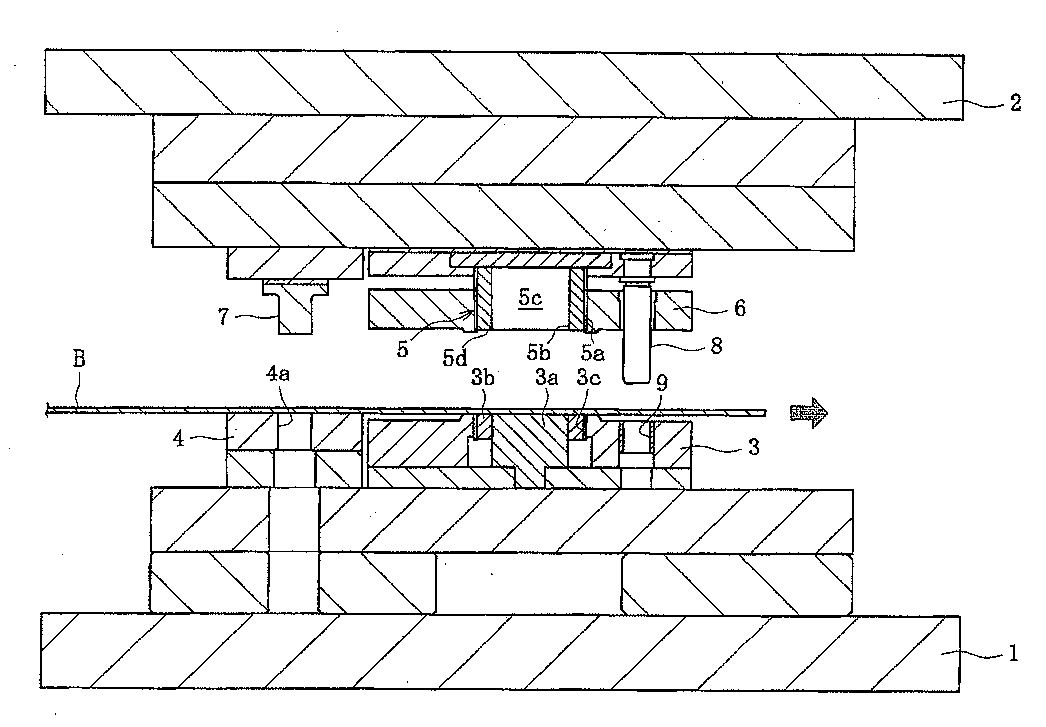
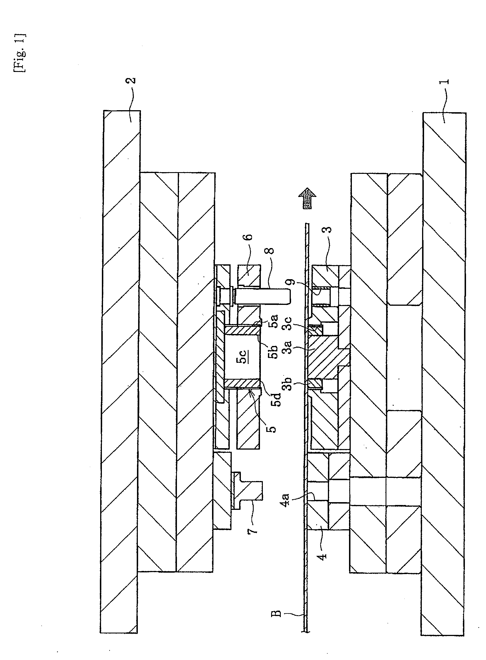
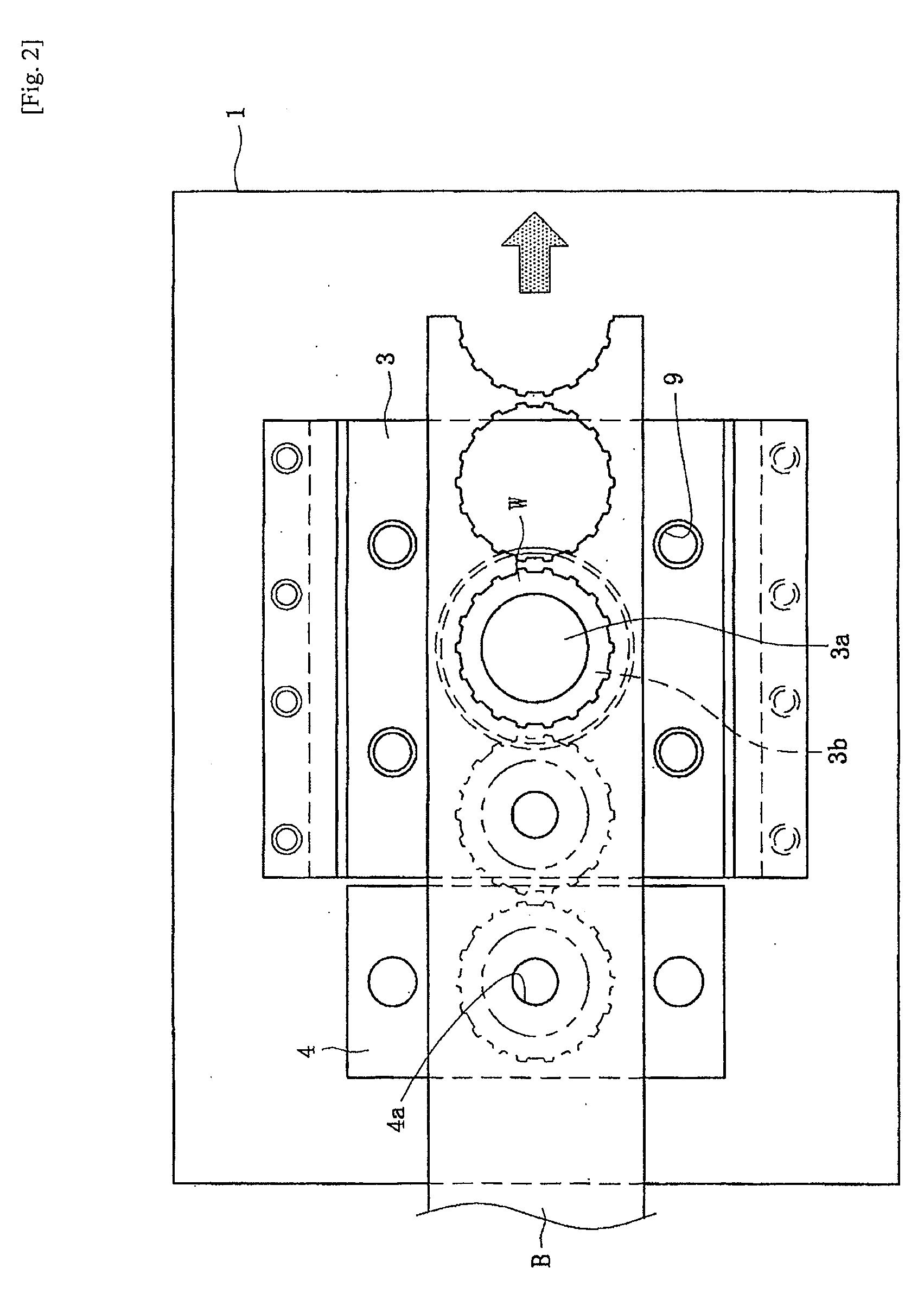
[0027]A punch working apparatus in accordance with one preferred embodiment is for manufacturing annular products (e.g. clutch plates of a multiple disc clutch) by punching a metal sheet material “B” and is especially for so-called “compound dies” in which both outer and inner circumferential punching works of the sheet material “B” are simultaneously performed. Such an example punching apparatus comprises as shown in FIG. 1 a lower mold frame 1 on which a die 3 and a sub-die 4, etc. are mounted, and an upper mold frame 2 on which a punch 5 and a sub-punch 7, etc. are mounted.

[0028]In a preferred embodiment, the sheet material “B” is a belt-shaped continuous material for example intermittently uncoiled by an uncoiler from a coiled material via a leveler feeder. The sheet material “B” is fed toward the right in FIG. 1 and laid on the sub-die 4 and the die 3 so as to be punched by the sub-die 7 and the punc...


PUM

PropertyMeasurementUnit
internal stressaaaaaaaaaa
pressureaaaaaaaaaa
outer circumferenceaaaaaaaaaa

Abstract

Embodiment, punch working apparatus has a first mold frame on which a die is mounted, a second mold frame movable toward and away from the first mold frame and a punch mounted on the first mold frame for simultaneously performing both outer and inner circumferential punching works on a sheet material between the frames, the punch containing resulted scraps in a space defined therewithin. A sub-punch is also provided, and punches an aperture having a predetermined configuration at a position of the sheet material that ends up as part of the scrap formed by and contained within the punch.

Description

CROSS-REFERENCE TO RELATED APPLICATIONS[0001]The present application is based on and claims priority under 35 U.S.C. § 119 to Japanese Patent Application Serial No. 2006-303494, filed on Nov. 9, 2006, the entire contents of which are expressly incorporated by reference herein.BACKGROUND[0002]1. Field of the Invention[0003]The present invention relates to a punch working apparatus and method for performing both outer and inner circumferential punching works on a sheet material.[0004]2. Description of the Related Art[0005]Japanese Laid-open Patent Publication No. 2006-239711 discloses an example of a punching apparatus having so-called “compound dies” in which both outer and inner circumferential punching works are simultaneously performed. The disclosed apparatus comprises a lower mold frame on which a female shearing mold (die) and an upper mold frame movable toward and away from the lower mold frame. The upper mold frame includes a male shearing mold (punch) for simultaneously perf...

Claims


Application Information

Patent Timeline
Patent Type & Authority Applications(United States)
IPC IPC(8): B26F1/02B26D7/18B26D7/00
CPCB21D28/02B21D53/20B21D45/06Y10T83/04Y10T83/8828
Inventor IWASHITA, YOSHIHIROSUZUKI, TETSUYA
Owner FCC KK
Why Eureka
Try Eureka