
Ferrofluidic cooling and acoustical noise reduction in magnetic stimulators

a technology of magnetic stimulators and acoustic noise reduction, which is applied in the field of magnetic stimulation, can solve the problems of increasing complexity of operation and overall cost, affecting the cooling effect of magnetic stimulators, and generating heat for magnetic devices,

Inactive Publication Date: 2008-05-15
NEURONETICS
View PDF26 Cites 94 Cited by
  • Summary
  • Abstract
  • Description
  • Claims
  • Application Information

AI Technical Summary

Benefits of technology

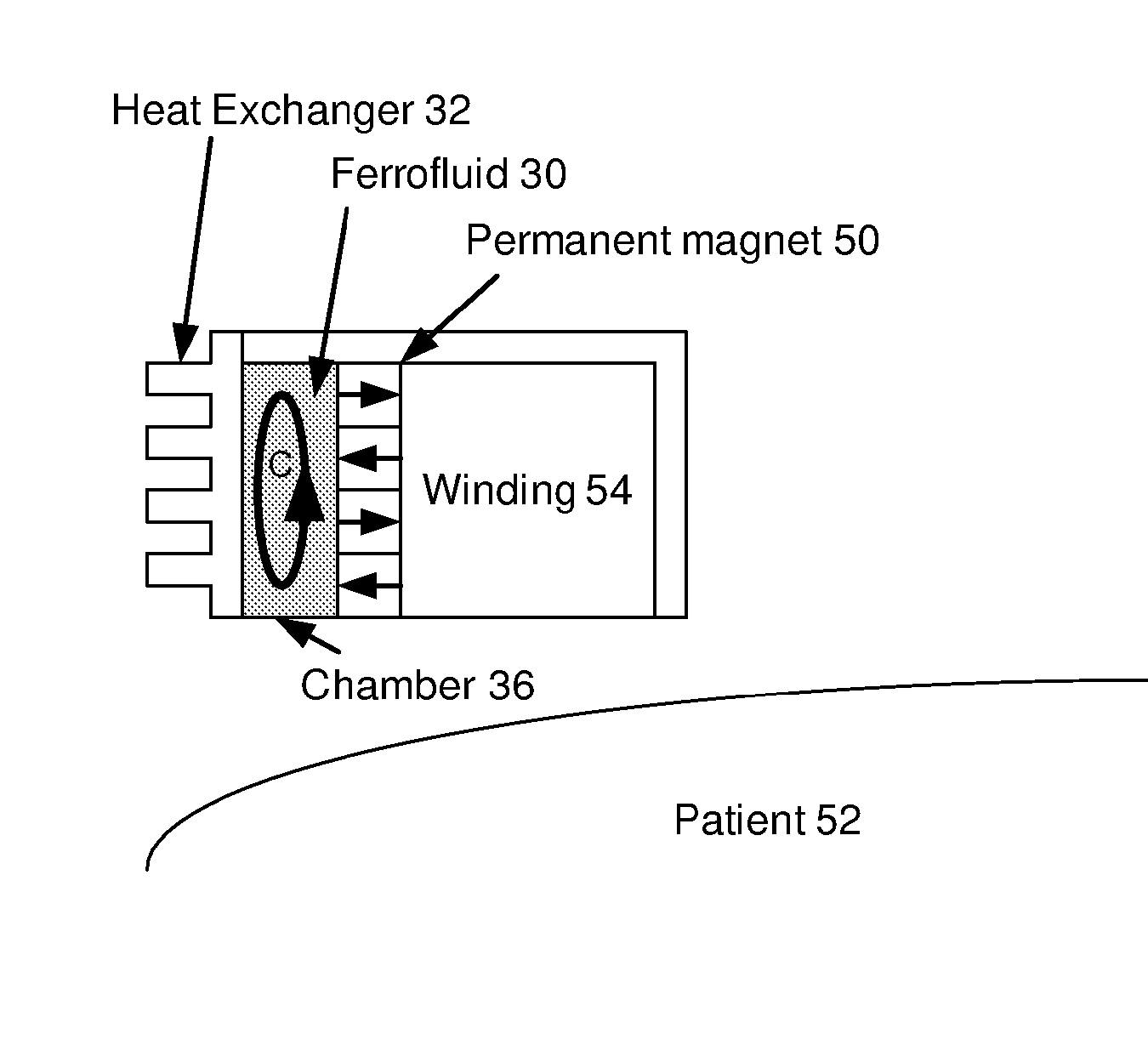
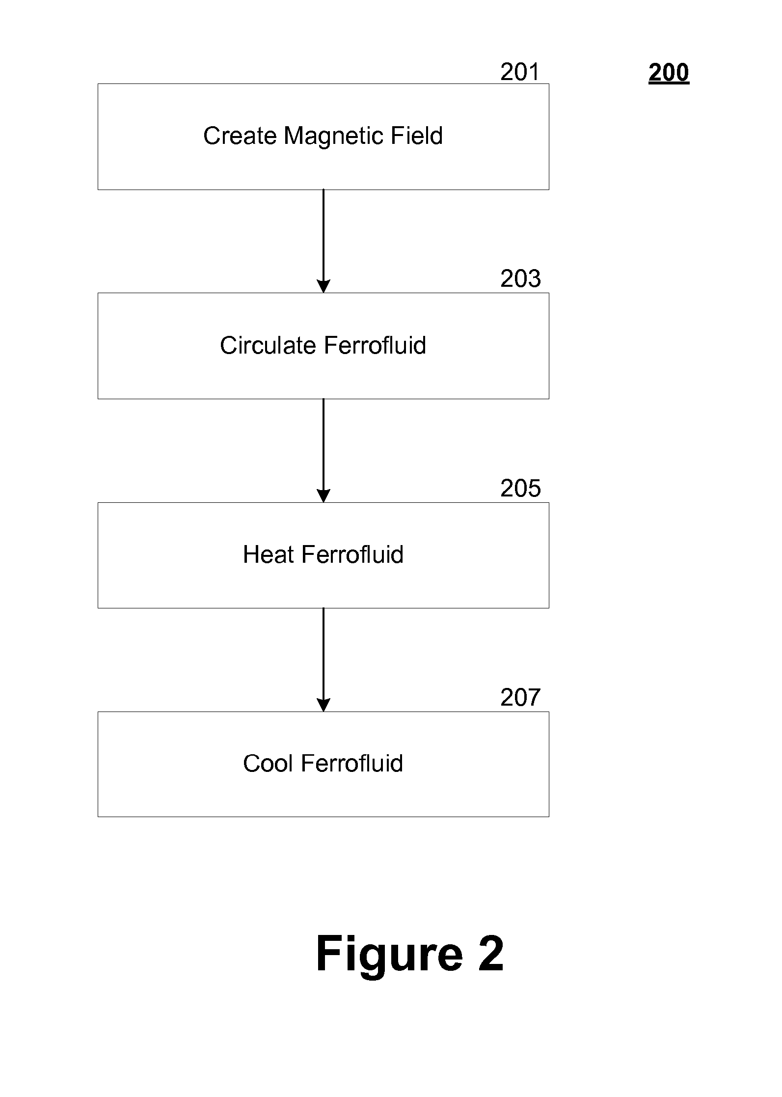
The patent describes an apparatus, system, and method for cooling a magnetic device using a ferrofluid. The apparatus has a housing that is attached to the magnetic device and contains a ferrofluid to cool it. The ferrofluid cools the device by convection caused by the magnetic field. The technical effect of this invention is to improve the cooling efficiency of magnetic devices.

Problems solved by technology

Magnetic devices tend to generate heat because of resistive losses in the coil(s) that generate magnetic fields(s), and the amount of heat generated is proportional to the amount of power consumed by the device.
Thus, high-voltage magnetic devices that consume large amounts of power, such as those used in magnetic stimulation therapy, can become very hot when in operation.
These additional requirements increase complexity of operation and overall cost, and are best avoided when possible.
Such an arrangement therefore adds to the time required to perform a treatment, which is undesirable for both the patient and the health practitioner.
This arrangement is also undesirable because of the added expense associated with the purchase and maintenance of an additional magnetic stimulation device.
Furthermore, additional time is required of the patient and health practitioner, as the second magnetic device will need to be set-up and / or calibrated to perform magnetic stimulation therapy on the patient.
Because the set-up and / or calibration steps provide opportunities for operator error, requiring the operator to perform such steps multiple times may decrease the overall safety level of the treatment.
For example, both mechanisms require additional moving parts (e.g., fans, cooling mechanisms such as a refrigeration or heat exchange unit, etc.), which add to the cost and complexity of the magnetic device.
Furthermore, the additional moving parts add to the potential for a device malfunction.
The changing magnetic field causes windings of the coil to experience hoop stresses that intermittently stress the windings, which causes a sharp acoustic click.
Such noise is especially pronounced in magnetic stimulation devices, as the therapeutic magnetic fields are created by pulsing the stimulation device's coil.
Such noise is problematic for patients, as the stimulation device is typically located in close proximity to the patient's head, and therefore the noise from the stimulation device may be uncomfortable.
In addition, a health practitioner who is repeatedly exposed to such noise may be adversely affected.
A conventional solution, placing earplugs in the patient's ears, is undesirable because it is an additional step to perform in the therapeutic process and does not solve the problem of the noise caused by the device in the treatment facility (e.g., physician's office, hospital, etc.).
In addition, the use of earplugs is undesirable because some psychiatric or young patients may be uncooperative, and therefore the use of earplugs unnecessarily complicates the procedure.
However, such noise reduction techniques have the disadvantage of adversely affecting heat transfer for cooling.
However, such air pockets also have the characteristic being poor conductors of heat.
Thus, if such a noise reduction technique is used, the magnetic stimulation device cannot be adequately cooled.
Attempting to mitigate such a dilemma by placing acoustical material, or forming a partial vacuum, around a cooling system that is itself arranged around a magnetic device is undesirable because of the added size, cost and complexity of the resulting device.
Furthermore, a mismatch in sound velocity may also cause the reflection of some of the sound waves.
Unfortunately, even the ferrofluid solution used in connection with speakers has disadvantages that may render it unsuitable for use with high voltage magnetic devices, such as a magnetic stimulation device.
For example, the ferrofluid used in connection with speaker cooling, while a dielectric when exposed to normal speaker-level voltages, may be unable to maintain dielectric isolation at the higher voltage levels used in connection with a magnetic stimulation device.
As a result, arcing or other problems may occur.

Method used


Image

  • Ferrofluidic cooling and acoustical noise reduction in magnetic stimulators
  • Ferrofluidic cooling and acoustical noise reduction in magnetic stimulators
  • Ferrofluidic cooling and acoustical noise reduction in magnetic stimulators

Examples


Embodiment Construction

[0016] The subject matter of the present invention is described with specificity to meet statutory requirements. However, the description itself is not intended to limit the scope of this patent. Rather, the inventors have contemplated that the claimed subject matter might also be embodied in other ways, to include different steps or elements similar to the ones described in this document, in conjunction with other present or future technologies. Moreover, although the term “step” may be used herein to connote different aspects of methods employed, the term should not be interpreted as implying any particular order among or between various steps herein disclosed unless and except when the order of individual steps is explicitly described.

[0017] Magnetic Device Overview

[0018] As is well known to those skilled in the art, the magnitude of an electric field induced on a conductor is proportional to the rate of change of magnetic flux density across the conductor. When an electric fie...


PUM


Abstract

A ferrofluid chamber has a housing that is adapted to be coupled to a component that generates a magnetic field. A ferrofluid may disposed within the housing for cooling the component via convection of the ferrofluid that is induced by the magnetic field.

Description

REFERENCE TO RELATED APPLICATION [0001] This application is a division of U.S. patent application Ser. No. 11 / 130,657, filed May 17, 2005, entitled “FERROFLUIDIC COOLING AND ACOUSTICAL NOISE REDUCTION IN MAGNETIC STIMULATORS”.FIELD OF THE INVENTION [0002] The invention relates to the field of magnetic stimulation. Specifically, the invention relates to cooling a magnetic stimulation device. In addition, the invention relates to acoustically insulating such a magnetic stimulation device. BACKGROUND OF THE INVENTION [0003] Magnetic devices are used in many applications, such as in magnetic stimulation devices, speakers and so forth. Magnetic devices tend to generate heat because of resistive losses in the coil(s) that generate magnetic fields(s), and the amount of heat generated is proportional to the amount of power consumed by the device. Thus, high-voltage magnetic devices that consume large amounts of power, such as those used in magnetic stimulation therapy, can become very hot w...

Claims


Application Information

Patent Timeline
Patent Type & Authority Applications(United States)
IPC IPC(8): A61N2/00A61N1/00
CPCA61N2/006H01F27/105H01F7/202F28D2021/0029
Inventor RIEHL, MARK EDWARDGHIRON, KENNETH
Owner NEURONETICS
Learn More