
Intervertebral prosthetic devices and surgical methods

a technology for prosthetic joints and vertebrae, applied in the field of spinal implants and methods, can solve the problems of predisposing neighboring spinal motion segments to rapid deterioration, and lack of mobility, and achieve the effect of increasing stress on adjacent spinal motion segments

Inactive Publication Date: 2008-05-15
WARSAW ORTHOPEDIC INC
View PDF26 Cites 36 Cited by
  • Summary
  • Abstract
  • Description
  • Claims
  • Application Information

AI Technical Summary

Benefits of technology

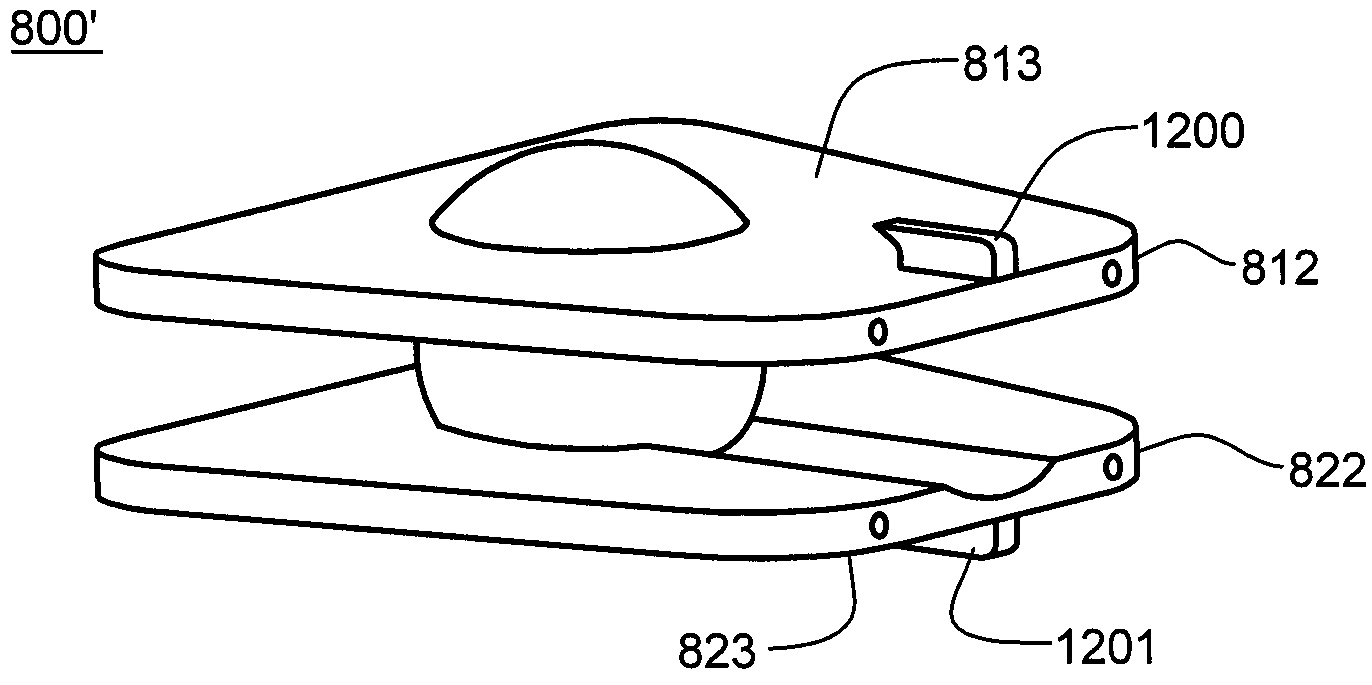
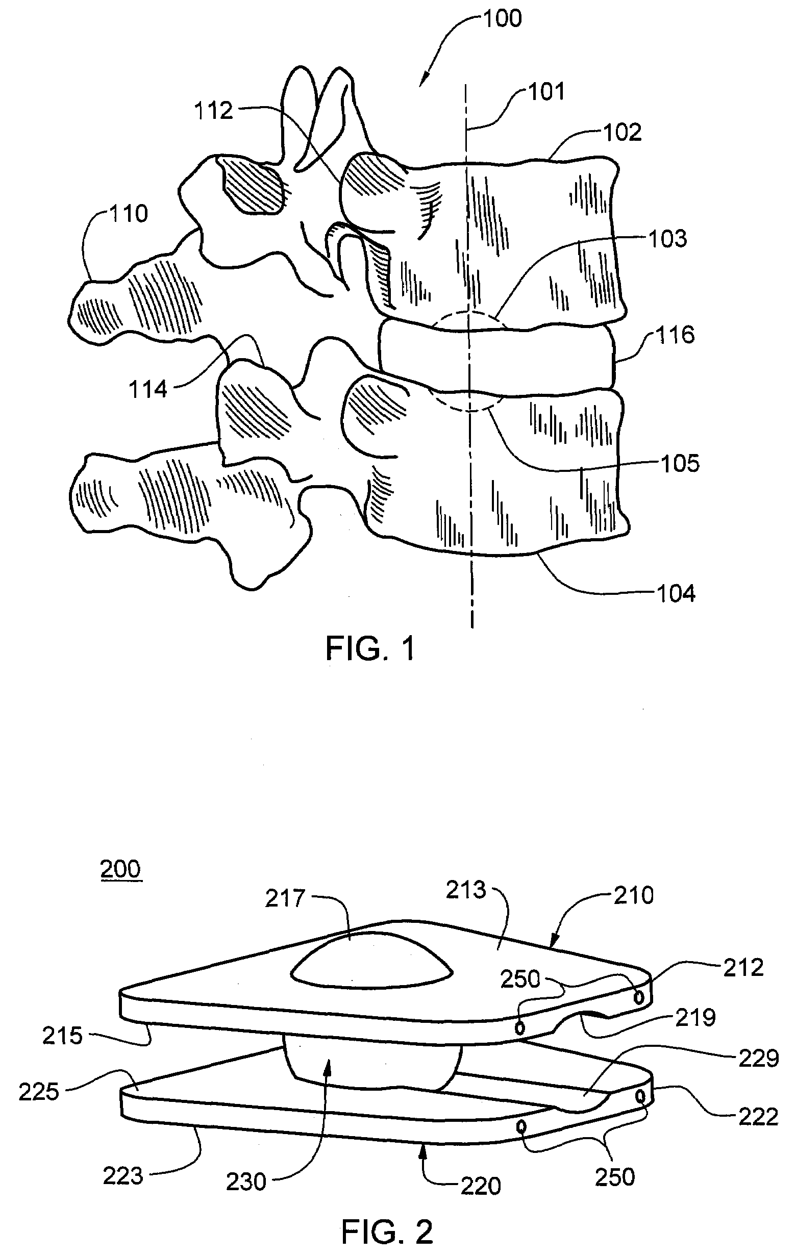
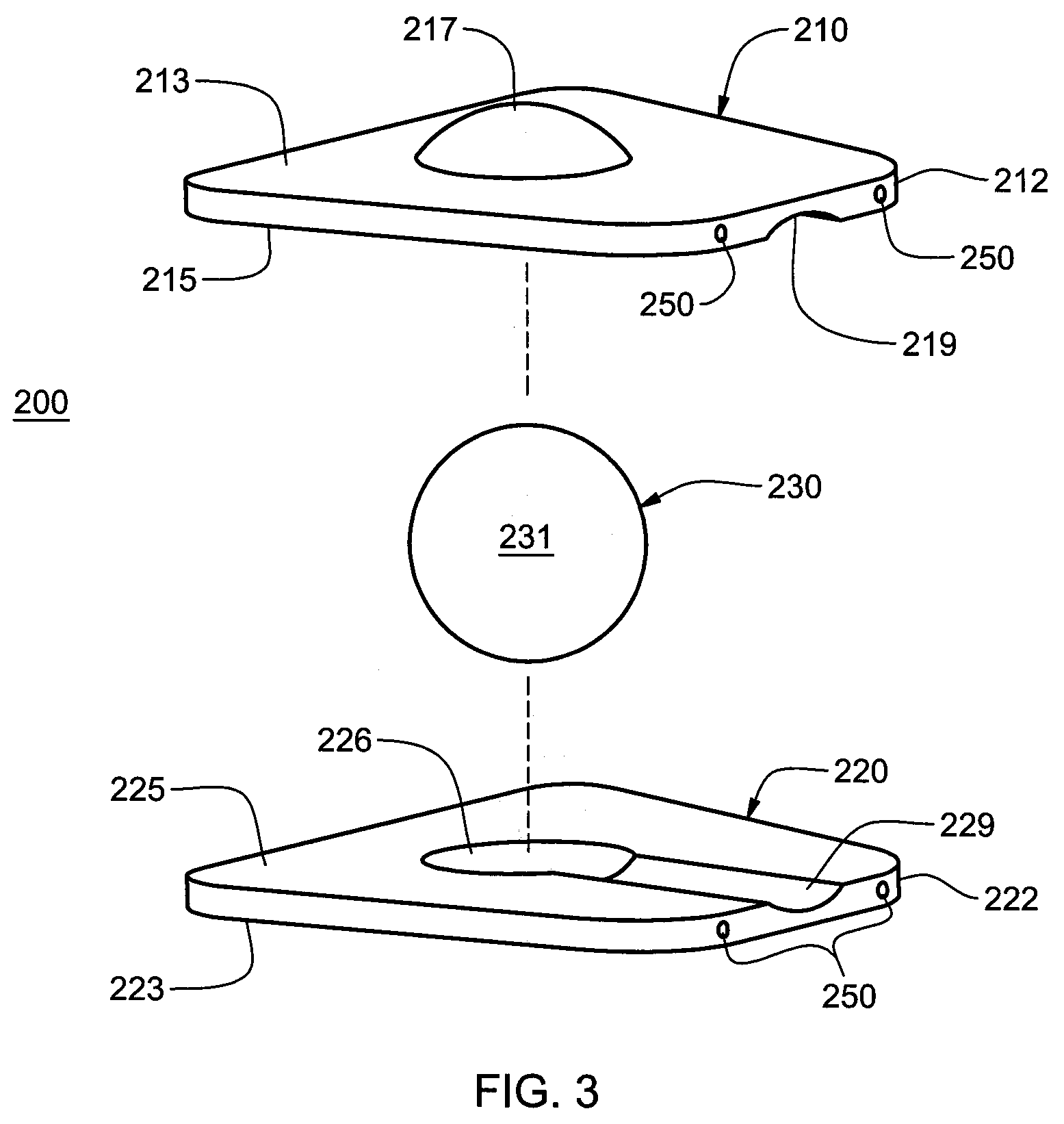
The present invention provides an intervertebral prosthetic device that includes first and second components that are designed to engage adjacent vertebral bodies. The first component has a first spherical segment that is positioned within a nuclear recess in the first vertebral body when the device is implanted between the two vertebral bodies. The second component has a second spherical segment that is positioned within a nuclear recess in the second vertebral body. The two components are connected by an articulation member that interfaces the two components and allows for articulating motion. The device can be inserted through a window in a minimally invasive surgical procedure. The technical effects of this invention include improved spinal mobility, reduced damage to the spinal column, and improved patient outcomes.

Problems solved by technology

Spinal fusion procedures, however, have raised concerns in the medical community that the biomechanical rigidity of the intervertebral fusion may predispose neighboring spinal motion segments to rapid deterioration.
Such lack of mobility tends to increase stress on adjacent spinal motion segments.

Method used


Image

  • Intervertebral prosthetic devices and surgical methods
  • Intervertebral prosthetic devices and surgical methods
  • Intervertebral prosthetic devices and surgical methods

Examples


Embodiment Construction

[0033]This disclosure relates to intervertebral disc prostheses for anterior, lateral or posterior insertion, either direct or indirect. For purposes of promoting and understanding the principles of this disclosure, reference is made hereinbelow to the anterior insertion embodiments, or examples, illustrated in the drawings and specific language is used to describe the same. It will nevertheless be understood that no limitation of the scope of the disclosure is thereby intended. Any alterations and further modifications to the described embodiments, and any further applications of the principles of disclosure as described herein are contemplated as would normally occur to one skilled in the art to which this disclosure relates. As such, individual features of separately described embodiments can be combined to form additional embodiments.

[0034]Provided herein are various intervertebral prosthetic devices (i.e., articular disc prostheses) and methods of implanting the same. In the va...


PUM

PropertyMeasurementUnit
center of rotationaaaaaaaaaa
biocompatibleaaaaaaaaaa
radiusaaaaaaaaaa

Abstract

Intervertebral prosthetic devices and methods of implanting the same within an intervertebral space between adjacent vertebral bodies are provided. One device includes first and second components, each configured to engage a respective one of the adjacent vertebral bodies. Each component includes a vertebral support plate with a spherical segment protruding therefrom. The spherical segments are disposed to reside within nuclear recesses in the adjacent vertebral bodies when the device is implanted in the intervertebral space, and are configured with a common center of rotation which aligns with the natural axis of rotation of the adjacent vertebral bodies. An articulation member, which interfaces the first and second vertebral support plates, may be an articular ball and respective concave articular surface regions in the plates, or alternatively, a convex articular surface and a respective concave articular surface in the vertebral support plates of the first and second components.

Description

CROSS-REFERENCE TO RELATED APPLICATIONS [0001]This application contains subject matter which is related to the subject matter of the following applications, which are hereby incorporated herein by reference in their entirety:[0002]“Intervertebral Prosthetic Devices and Methods”, Eric Steven Heinz, U.S. Ser. No. 11 / 398,874, filed Apr. 6, 2006;[0003]“Intervertebral Spinal Implant Devices and Methods of Use”, Heinz et al., U.S. Ser. No. 11 / 343,954 filed Jan. 31, 2006;[0004]“Intervertebral Prosthetic Disc”, Heinz et al., U.S. Ser. No. 11 / 343,935, filed Jan. 31, 2006;[0005]“Articular Disc Prosthesis and Method for Implanting the Same”, Eisermann et al., U.S. Ser. No. 10 / 412,700, filed Apr. 11, 2003, and published on Oct. 30, 2003 as Patent Application Publication No. US 2003 / 0204261 A1;[0006]“Intervertebral Prosthetic Joint”, Eisermann et al., U.S. Ser. No. 10 / 620,529, filed Jul. 16, 2003, and published on Apr. 15, 2004 as Patent Application Publication No. US 2004 / 0073312 A1; and[0007]“...

Claims


Application Information

Patent Timeline
Patent Type & Authority Applications(United States)
IPC IPC(8): A61F2/44
CPCA61F2/4425A61F2310/00796A61F2002/30242A61F2002/30663A61F2002/30785A61F2002/30836A61F2002/30878A61F2002/30884A61F2002/30925A61F2002/443A61F2230/0071A61F2310/00017A61F2310/00023A61F2310/00029A61F2310/00449A61F2/4611
Inventor FRANCIS, THOMAS J.
Owner WARSAW ORTHOPEDIC INC
Learn More