Wireless-enabled tightening system for fasteners and a method of operating the same

a technology of wireless and fastener, which is applied in the direction of screws, instruments, force/torque/work measurement apparatus, etc., can solve the problems of operator loss of place, risk, and operator loss of position, so as to avoid the loss of bolts or tighten bolts

a technology of wireless and fastener, which is applied in the direction of screws, instruments, force/torque/work measurement apparatus, etc., can solve the problems of operator loss of place, risk, and operator loss of position, so as to avoid the loss of bolts or tighten bolts

US20080115589A1Active Publication Date: 2008-05-22GENERAL ELECTRIC CO

Image

  • Wireless-enabled tightening system for fasteners and a method of operating the same
  • Wireless-enabled tightening system for fasteners and a method of operating the same
  • Wireless-enabled tightening system for fasteners and a method of operating the same

Examples


Embodiment Construction

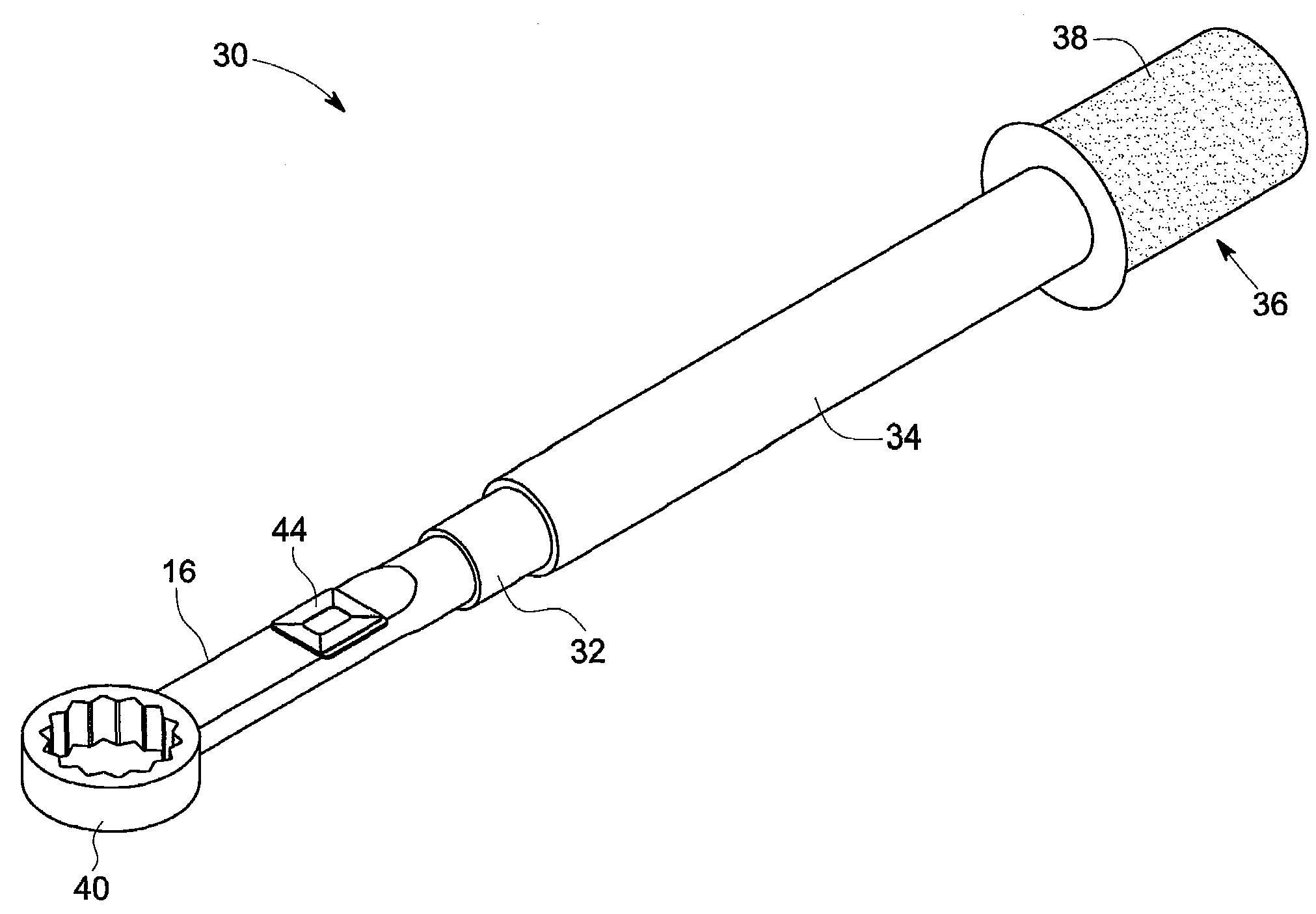
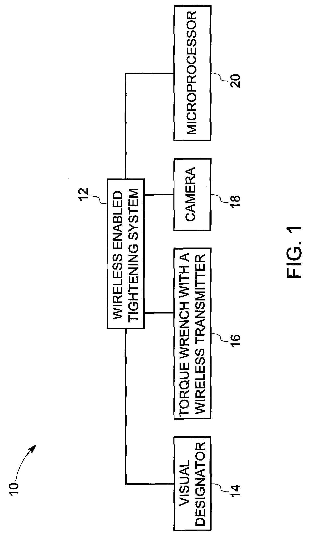
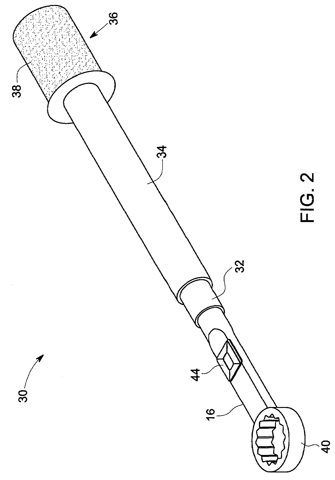
[0012]As discussed in detail below, embodiments of the present invention include a wireless-enabled tightening system for fasteners and a method of operating the same. As used herein, the term ‘wireless’ refers to a signal transmitted over a radio frequency or an ultrasonic frequency. Some non-limiting examples of the fasteners may include bolts and nuts. There are a number of fasteners that have to be tightened in a sequential pattern during assembly of various types of equipment, such as aircraft engine assemblies. The wireless-enabled tightening system disclosed herein allows for sequential tightening and tracking of the fasteners in such assemblies with minimal errors.

[0013]FIG. 1 is a block diagram representation of components of a wireless-enabled tightening system 10 used for tightening a series of fasteners on a workpiece in a sequential pattern. A system 12 includes a visual designator 14 configured to project an indicator, such as a spotlight, onto the fastener in the work...


PUM

PropertyMeasurementUnit
torqueaaaaaaaaaa
colorsaaaaaaaaaa
coloraaaaaaaaaa

Abstract

A wireless-enabled tightening system for fasteners is disclosed. The system includes a visual designator configured to project an indicator onto a workpiece. The system also includes a torque wrench comprising a wireless transmitter and a means for identifying whether the correct torque has been applied to a fastener on the workpiece and configured to provide a feedback for a user. The system also includes a camera configured to capture an image of the workpiece when an appropriate amount of torque has been applied to the fastener. The system further includes a microprocessor for determining sequence of the fastener and identifying the tightened fastener.

Description

BACKGROUND[0001]The invention relates generally to process control systems, and more particularly to automatic radio frequency identification systems.[0002]The construction of large mechanical assemblies, such as aircraft engines, often requires a rigorous process of tightening nuts and bolts in a particular order or sequence. Because the sequence in which fasteners are tightened is important, it is necessary for the assembly technician to keep track of which nuts or bolts have been tightened and to identify which fastener to tighten next.[0003]In addition to being tightened in a specific order, assembly processes also often require the technician to retorque a nut or a bolt a different times during the assembly sequence. However, this technique is cumbersome and involves risks due to human error. There are several steps in the assembly process that may cause an operator to lose his place and miss a bolt or to tighten a bolt out of sequence.[0004]Therefore, there is a need for an im...

Claims


Application Information

Patent Timeline
22 May 2008
Publication
US20080115589A1
IPC
G01L5/24; F16B31/02
CPC
B25B21/00; F16B31/02; B25B23/14
Inventors
DEROSE, LYNN ANN; BENNETT, JANET SUE