Liquid crystal display device and apparatus with display function

Inactive Publication Date: 2008-05-22
SANYO ELECTRIC CO LTD +1
View PDF6 Cites 10 Cited by
  • Summary
  • Abstract
  • Description
  • Claims
  • Application Information

AI Technical Summary

Benefits of technology

[0008]It is an object of the present invention to provide an arrangement that enables to provide improved stereoscopic appearance of an image to be displayed in a multilayered manner by changing the number of spacers to be disposed between liquid crysta

Problems solved by technology

The publication, however, does not disclose a specific a

Method used


Image

  • Liquid crystal display device and apparatus with display function
  • Liquid crystal display device and apparatus with display function
  • Liquid crystal display device and apparatus with display function

Examples


Embodiment Construction

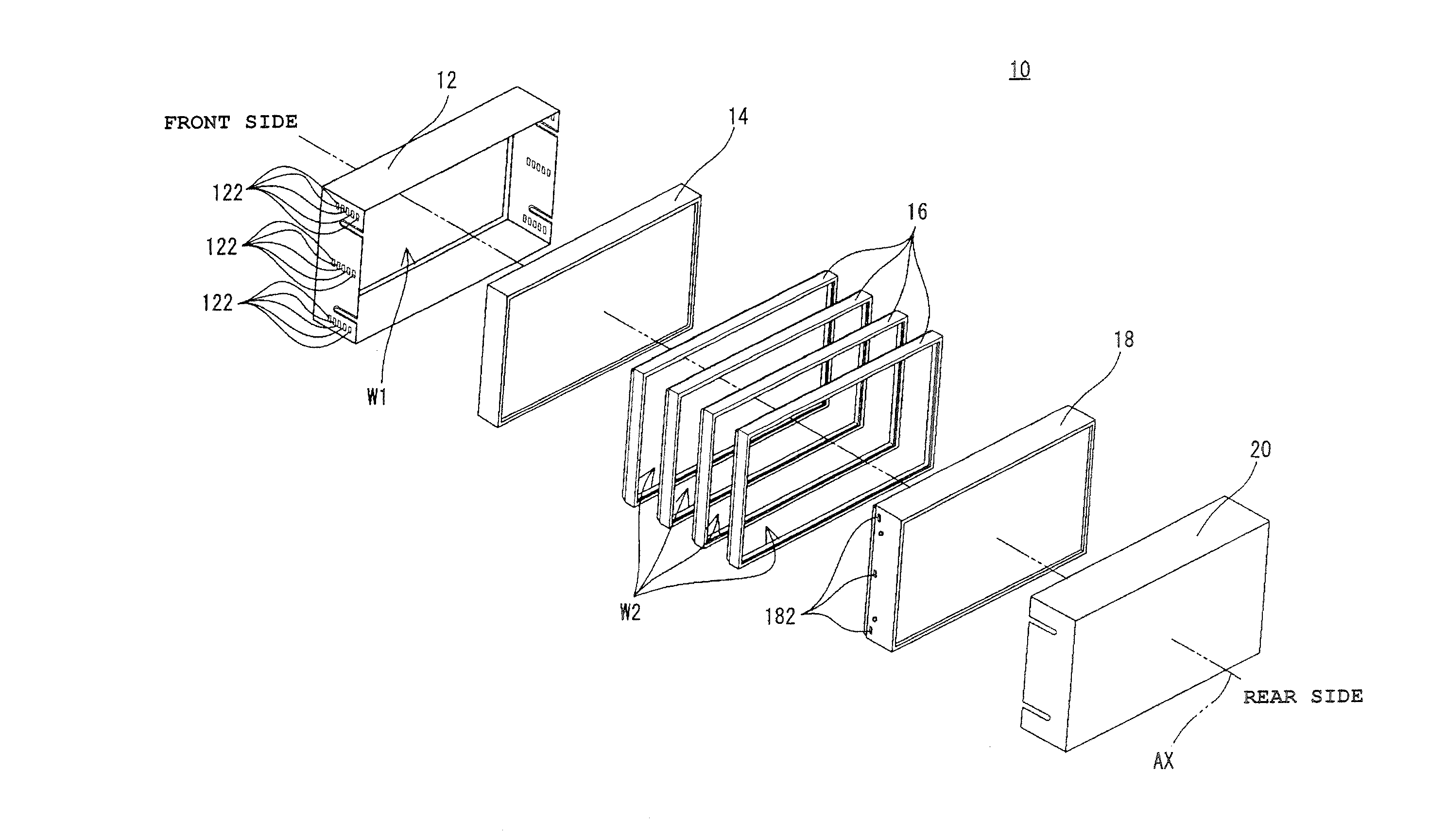
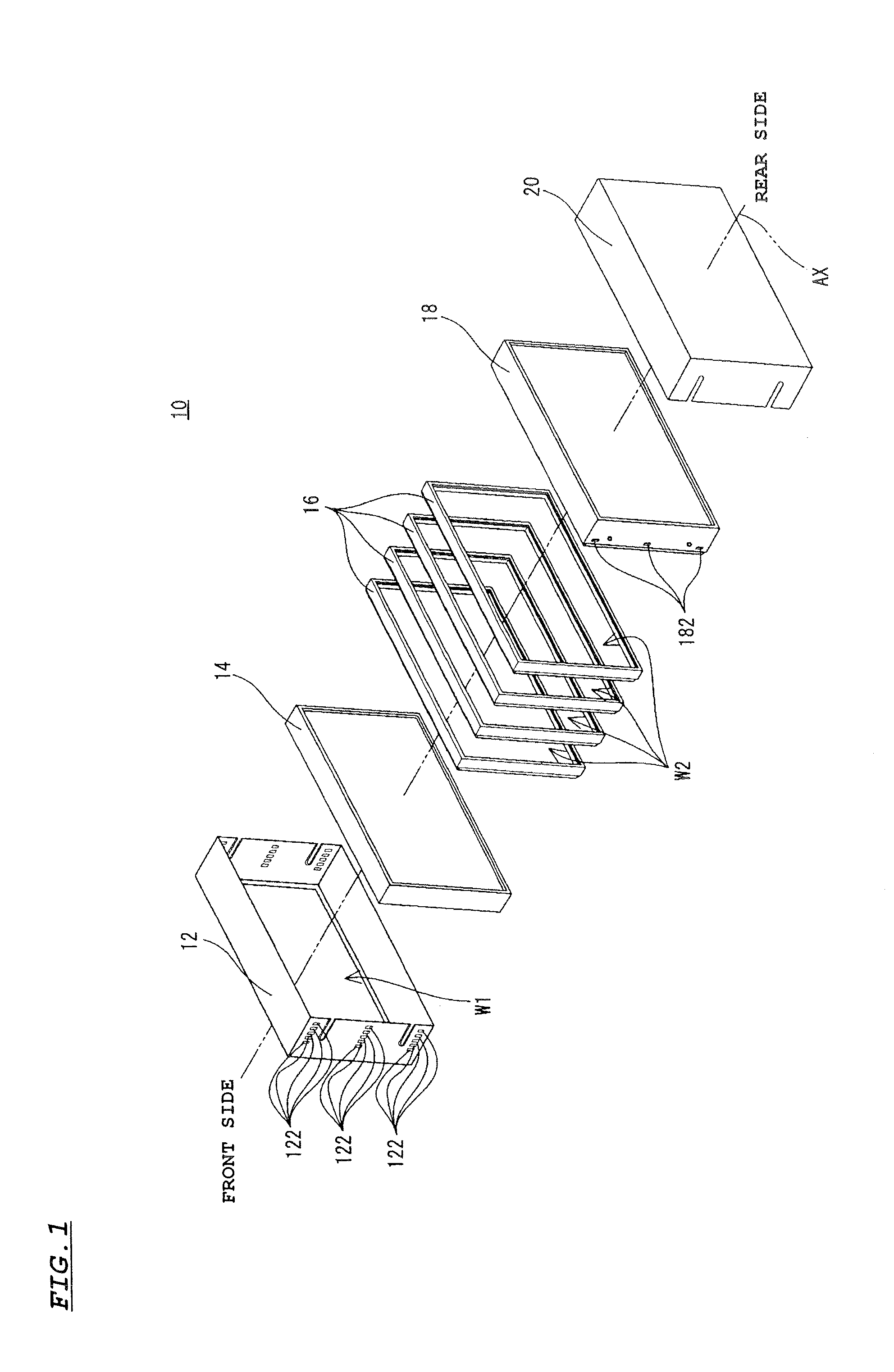
[0036]Referring to FIG. 1, a liquid crystal display device 10 embodying the invention includes a front cover 12, a front-side liquid crystal panel 14, multiple (in this embodiment, four) spacers 16, 16, . . . , a rear-side liquid crystal panel 18, and a rear cover 20.

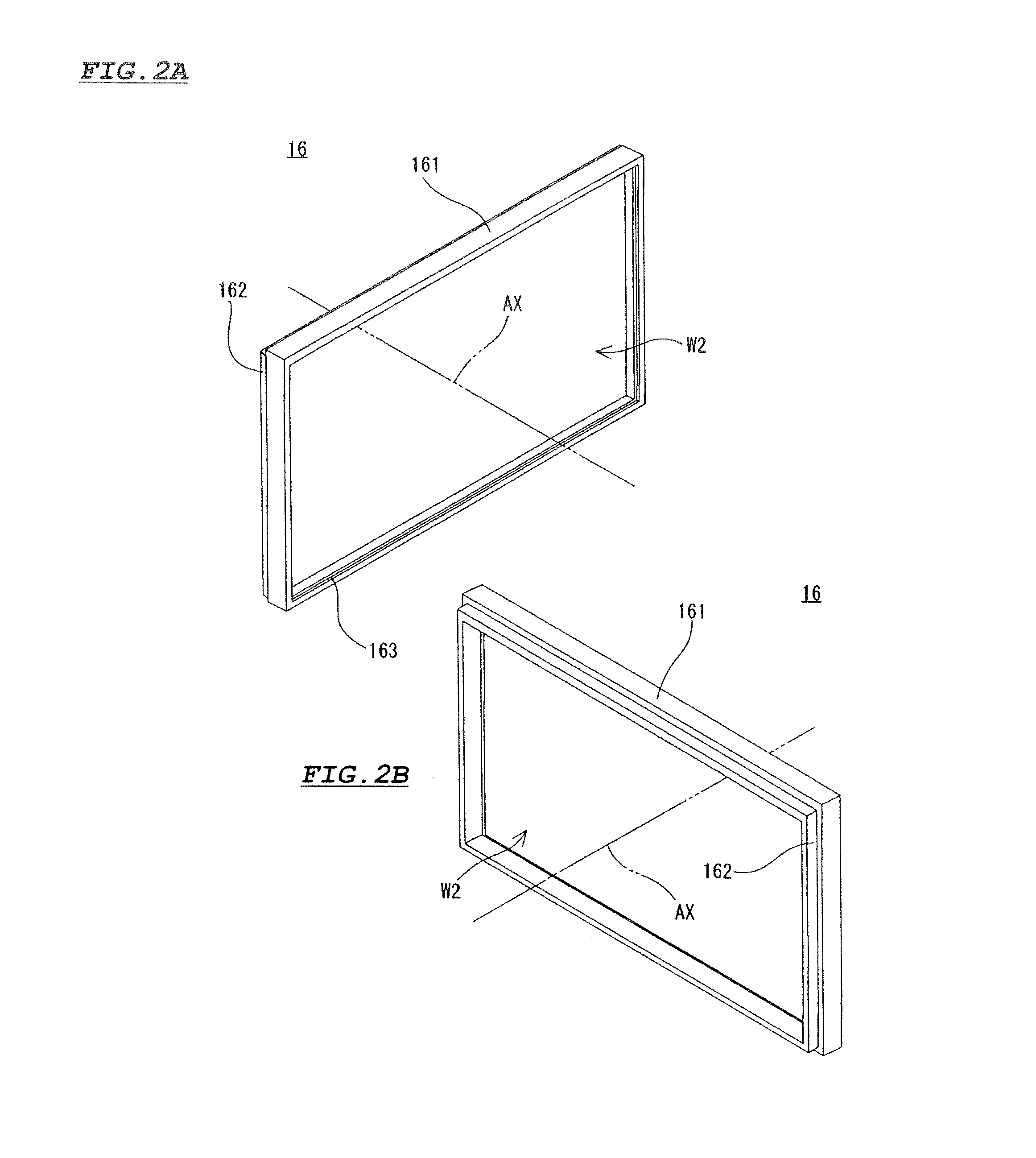
[0037]The liquid crystal panels 14 and 18 each has a rectangular plate-like shape. The size of a primary plane, and the size of a display screen to be mounted on the primary plane are identical between the liquid crystal panels 14 and 18. The spacers 16, 16, . . . , are each made of a synthetic resin, and formed into a rectangular frame shape. The size of the spacer 16 is substantially the same as the size of the primary plane of the liquid crystal panel 14 or 18. The size of a window W2 defined by the frame of the spacer 16 is substantially the same as the size of the display screen.

[0038]The liquid crystal panel 14, the spacers 16, 16, . . . , and the liquid crystal panel 18 are laid one over the other in the directio...


PUM


Abstract

Two liquid crystal panels are laid one over the other in a state that each of the liquid crystal panels is oriented in a forward direction. At least one spacer is detachably provided between the two liquid crystal panels. The liquid crystal panels are positioned relative to each other by a plurality of through-holes arrayed in a thickness direction of the spacer by an interval corresponding to the thickness of the spacer, and a projection engageable in one of the through-holes.

Description

[0001]This application claims priority under 35 U.S.C. Section 119 of Japanese Patent Application No. 2006-313062 filed Nov. 20, 2006, entitled “LIQUID CRYSTAL DISPLAY DEVICE” and Japanese Patent Application No. 2007-265114 filed Oct. 11, 2007, entitled “LIQUID CRYSTAL DISPLAY DEVICE AND APPARATUS WITH DISPLAY FUNCTION”.BACKGROUND OF THE INVENTION[0002]1. Field of the Invention[0003]The present invention relates to a liquid crystal display device, and an apparatus, with a display function, including the liquid crystal display device, and more particularly to a liquid crystal display device and an apparatus, with a display function, including the liquid crystal display device, for e.g. outputting multiple images to be individually reproduced on multi-layered liquid crystal panels from the front side.[0004]2. Description of the Background Art[0005]In current days, a liquid crystal display device is incorporated in various apparatuses. In apparatuses such as game machines or amusement ...

Claims


Application Information

Patent Timeline
IPC IPC(8): G02F1/1347H04N13/395
CPCG02B27/2278G02F1/133308H04N13/0495G02F2001/133317G02F2201/46G02F1/1347H04N13/395G02B30/52G02F1/133317
Inventor FUJITA, TSUTOMUYOSHIDA, SHIGERUONO, TOMOYUKISAKAIDA, YUTAKA
Owner SANYO ELECTRIC CO LTD
Why Eureka
Try Eureka