Method and apparatus providing adaptive noise suppression

a solid-state imager and noise reduction technology, applied in the field of solid-state imager devices, can solve the problems of severe impact on image quality, increase in noise on image quality, and noise reduction of solid-state image sensors, so as to suppress (or remove) noise, without blurring the image, and suppress more noise

Active Publication Date: 2007-11-08
APTINA IMAGING CORP
View PDF10 Cites 34 Cited by
  • Summary
  • Abstract
  • Description
  • Claims
  • Application Information

AI Technical Summary

Benefits of technology

[0008] The exemplary noise filter could be applied either to each color separately in Bayer, Red / Green / Blue (RGB), Cyan / Magenta / Yellow / Key (CMYK), luminance / chrominance (YUV), or other color space. The invention suppresses (or removes) noise introduced by the pixel with digital algorithms without blurring the image. As noise scales with gain, it is possible to scale the correction such that more noise may be suppressed at higher gain levels. Noise suppression will improve both the visual appearance of the image (i.e., smoother surfaces and sharper edges), and later processing such as compression, allowing higher compression ratios.

Problems solved by technology

One of the most challenging problems for solid state image sensors is noise reduction, especially for sensors with a small pixel size.
The effect of noise on image quality increases as pixel sizes continue to decrease and may have a severe impact on image quality.
Specifically, noise impacts image quality in smaller pixels because of reduced dynamic range.
One of the ways of solving this problem is by improving fabrication processes; the costs associated with such improvements, however, are high.
There are many complicated noise reduction algorithms which reduce noise in the picture without edge blurring, however, they require huge calculating resources and cannot be implemented in a silicon-on-a-chip application.
One problem associated with local smoothing filters is that they do not distinguish between high frequency components that are part of the image and those created due to noise.
The utilization of these filters for image denoising, however, is impeded by the large volume of calculations required to process the image data.
Additionally, block artifacts and oscillations may result from the use of these filters to reduce noise.

Method used


Image

  • Method and apparatus providing adaptive noise suppression
  • Method and apparatus providing adaptive noise suppression
  • Method and apparatus providing adaptive noise suppression

Examples


Embodiment Construction

[0017] In the following detailed description, reference is made to the accompanying drawings, which form a part hereof and show by way of illustration specific embodiments in which the invention may be practiced. These embodiments are described in sufficient detail to enable those skilled in the art to practice the invention, and it is to be understood that other embodiments may be utilized, and that structural, logical, and electrical changes may be made without departing from the spirit and scope of the present invention. The progression of processing steps described is exemplary of the embodiments of the invention; however, the sequence of steps is not limited to that set forth herein and may be changed as is known in the art, with the exception of steps necessarily occurring in a certain order.

[0018] The term “pixel,” as used herein, refers to a photo-element unit cell containing a photosensor device and associated structures for converting photons to an electrical signal. For ...


PUM


Abstract

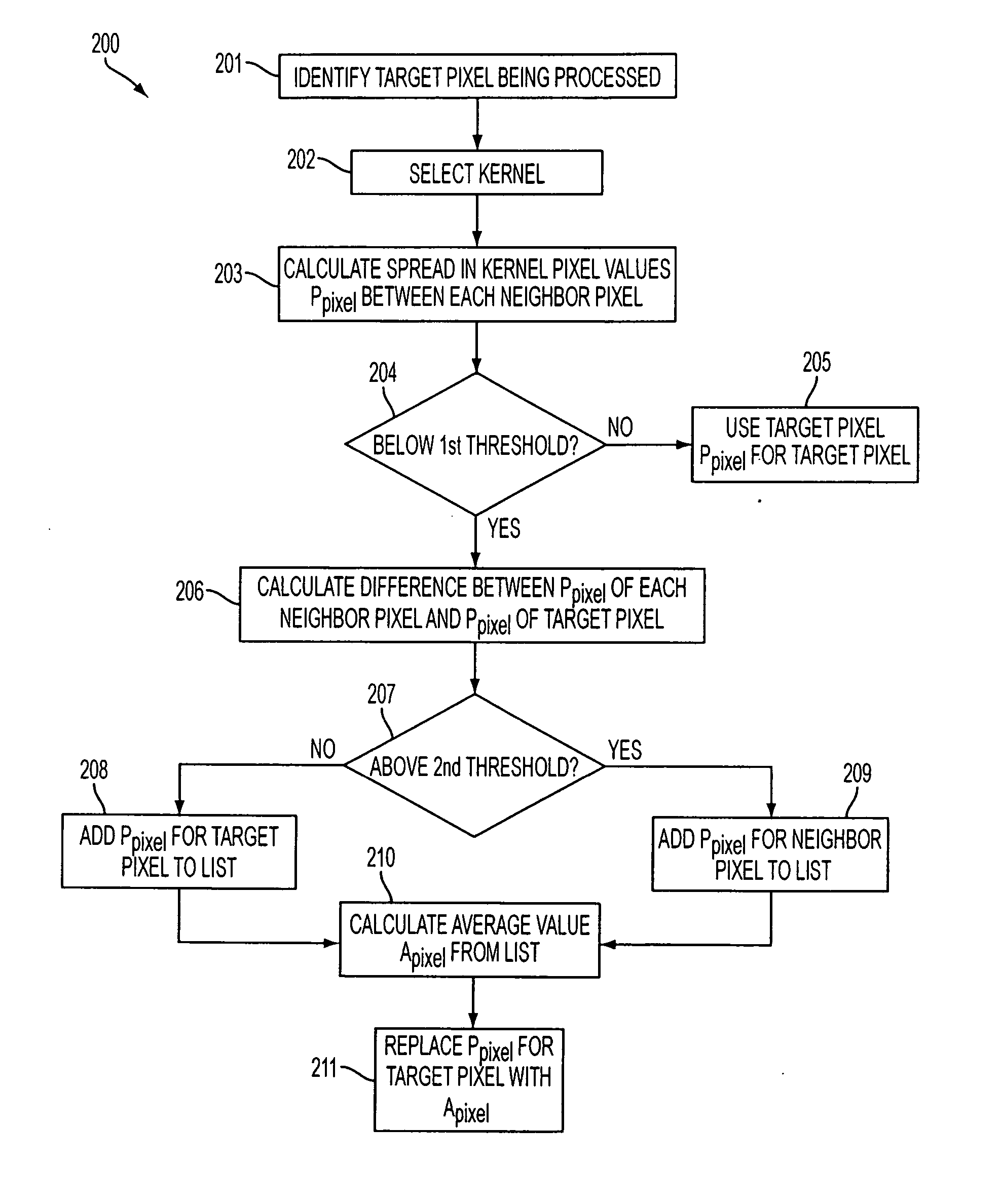
A method of reducing noise in an image including steps for obtaining a first value for a target pixel, obtaining a respective second value for each neighboring pixel surrounding the target pixel, identifying a spread for the second values, comparing the spread to a threshold value, and, if the spread if below the threshold value, calculating a new value using the second values, and replacing the first value with the new value.

Description

FIELD OF THE INVENTION [0001] The invention relates generally to the field of solid state imager devices, and more particularly to a method and apparatus for noise reduction in a solid state imager device. BACKGROUND OF THE INVENTION [0002] Solid state imagers, including charge coupled devices (CCD), CMOS imagers and others, have been used in photo imaging applications. A solid state imager circuit includes a focal plane array of pixel cells, each one of the cells including a photosensor, which may be a photogate, photoconductor or a photodiode having a doped region for accumulating photo-generated charge. [0003] One of the most challenging problems for solid state image sensors is noise reduction, especially for sensors with a small pixel size. The effect of noise on image quality increases as pixel sizes continue to decrease and may have a severe impact on image quality. Specifically, noise impacts image quality in smaller pixels because of reduced dynamic range. One of the ways o...

Claims


Application Information

Patent Timeline
Patent Type & Authority Applications(United States)
IPC IPC(8): G06K9/40H04N5/357H04N5/369H04N9/07H04N9/77
CPCG06T5/20H04N5/357H04N9/045G06T2207/20192G06T2207/10024G06T2207/20012G06T5/002H04N25/60H04N23/843H04N25/134
Inventor KRYDA, KENHARTMANN, MICHAEL
Owner APTINA IMAGING CORP
Why Eureka
Try Eureka