
Artifact management in rotational imaging

a rotational imaging and artifact management technology, applied in the field of artifact management in rotational imaging, can solve the problems of guidewire shadow, discontinuity or gap in information acquisition, guidewire shadow, etc., and achieve the effect of minimizing the effects of both seam line and guidewire shadow artifacts and improving image appearan

Active Publication Date: 2012-07-05
VOLCANO CORP
View PDF12 Cites 81 Cited by
  • Summary
  • Abstract
  • Description
  • Claims
  • Application Information

AI Technical Summary

Benefits of technology

[0006]The method described herein minimizes the effects of both the seam line and guidewire shadow artifacts by orienting the seam line artifact so that it overlaps the guidewire artifact in an intravascular image. The method reduces two discontinuous image artifacts in a display frame (the seam line and guidewire shadow) into a common rotational position, which results in a single traditionally tolerable gap in the information acquired and improved image appearance for an end user of the image. Another embodiment of the method is that a three dimensional dataset is rotationally registered to keep the guidewire shadow at a common rotational position throughout a longitudinal scan, thus insuring that a longitudinal cross-section or representation of the data along a plane that contains the longitudinal axis of the catheter (known as the ILD projection of a data set) only suffers from the guidewire shadow at a single slice angle. The method is applicable to any rotational imaging in which a periodic image discontinuity is evident.

Problems solved by technology

However, such a planar format includes a discontinuity in the data because of longitudinal displacement of the beam during rotation.
Such a seam line is a disadvantageous artifact of the planar format.
Such an artifact, generally known as a guidewire shadow, has traditionally been considered an unavoidable but tolerable discontinuity or gap in the information acquired.
However, this approach only minimizes the appearance of the seam line and does nothing to address the guidewire artifact.
There is currently no method known to minimize the effects of both the seam line and guidewire artifacts in an intravascular imaging modality.

Method used


Image

  • Artifact management in rotational imaging
  • Artifact management in rotational imaging
  • Artifact management in rotational imaging

Examples


Embodiment Construction

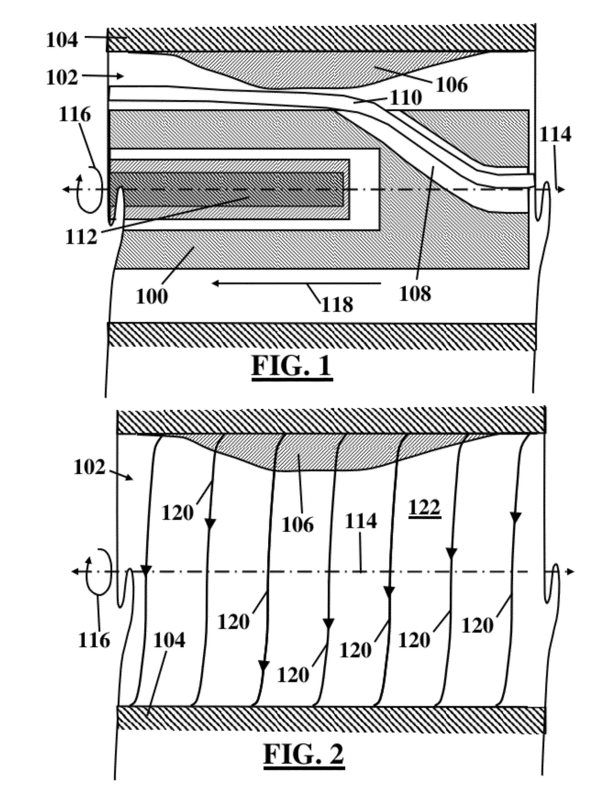
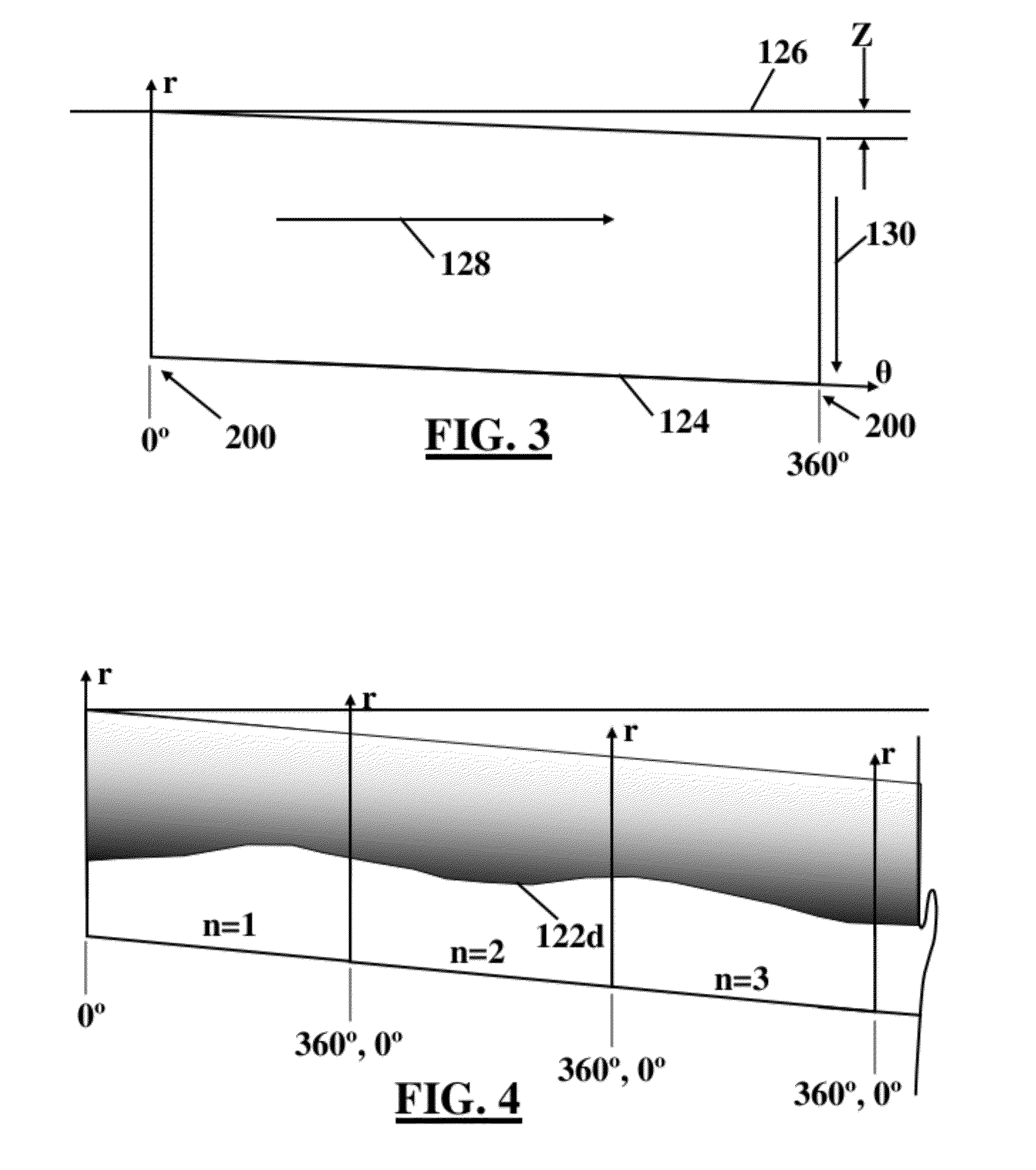
[0031]Language indicative of a relative geometric relationship between components includes use of the terms “proximal” and “distal” herein. In this context, “proximal” refers to an end of a component nearest to the medical practitioner during use and “distal” refers to the end of the component furthest from the medical practitioner during use. FIGS. 4-7 and 9-12B herein are line drawings representative of data acquired by a rotational imaging modality and may be representative of negative images of the actual acquired data. Darker areas in the line drawings represent typically brighter areas as would be displayed, for example, on a video monitor. Likewise, lighter areas in the line drawings represent typically darker areas as would be displayed; thus, a shadow is displayed as white space.

[0032]A method for managing artifacts in a rotational imaging system is disclosed herein. The rotational imaging system may be suitable for insertion into a lumen of any anatomical or mechanical con...


PUM


Abstract

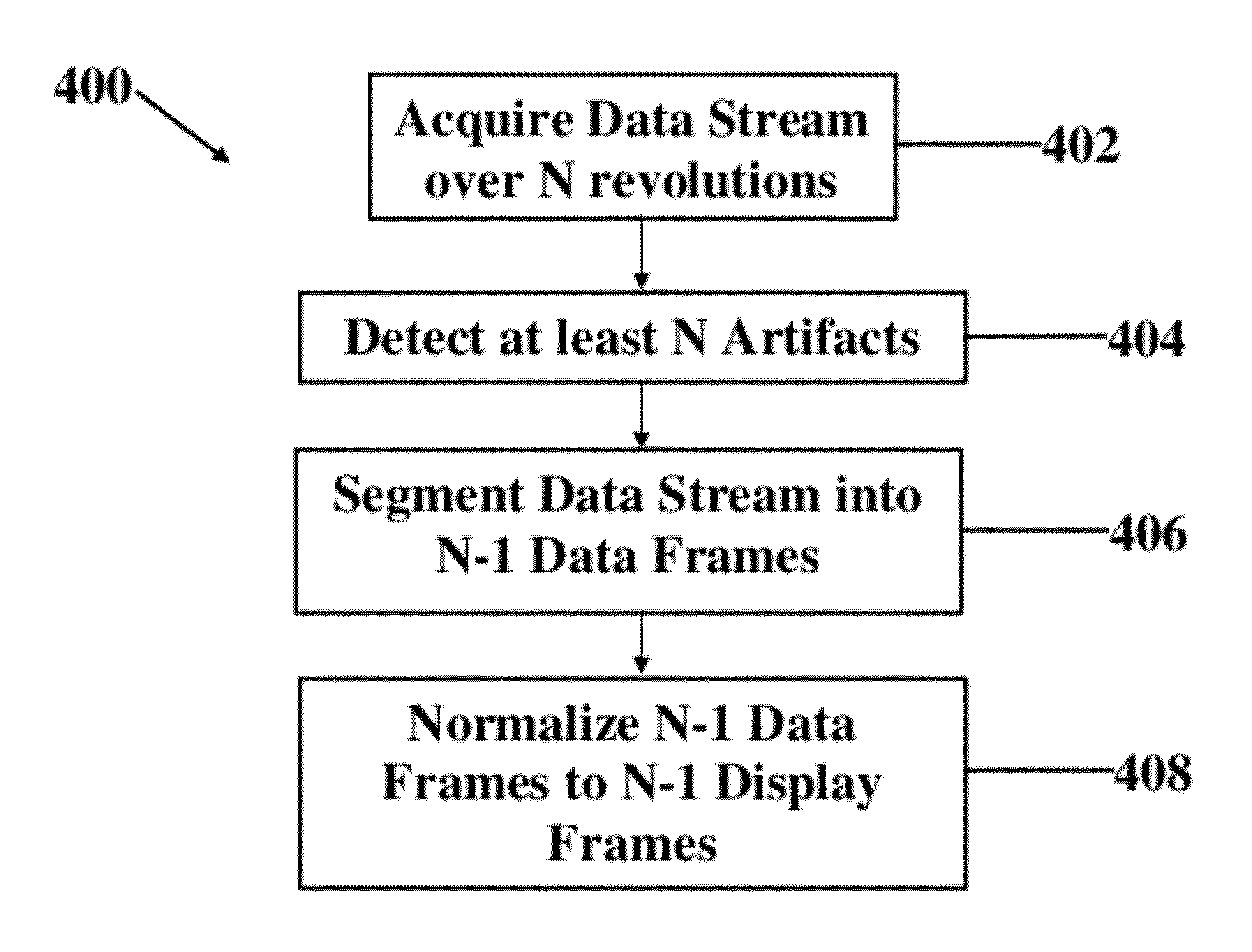
A method for artifact management in a rotational imaging system is presented. The method includes the steps of acquiring data employing a helical scanning pattern over N revolutions, where N is greater than 1, and detecting at least one artifact in the acquired data of each revolution. The method further includes segmenting the data acquired over N revolutions into N-1 data frames each bounded by at least one of the at least one artifacts.

Description

CROSS-RELATED APPLICATIONS[0001]Not Applicable.FIELD OF THE INVENTION[0002]The present invention relates generally to a method for overlapping artifacts in an in vivo imaging system. More particularly, the present invention pertains to a method for overlapping seam line and guidewire shadow artifacts in an in vivo intravascular imaging system having a rotational imaging catheter and one or more guidewires.BACKGROUND OF THE INVENTION[0003]Rotational intravascular imaging or sensing technologies, for example, optical coherence tomography (OCT), intravascular ultrasound (IVUS), near infrared (NIR) spectroscopy, and others typically employ point-scanning beam patterns in the shape of a helix, which captures information in rotational and longitudinal directions. A three-dimensional space scanned within a single rotational period generates information which is usually projected into a planar (2D) format for display on a video monitor or other display device. However, such a planar format ...

Claims


Application Information

Patent Timeline
Patent Type & Authority Applications(United States)
IPC IPC(8): G06K9/46G06K9/40
CPCG06T5/50G06T7/0081G06T7/0012G06T2207/10132G06T2207/30021G06T2207/10101A61B6/5258G06T2207/10072G06T2207/30101
Inventor KEMP, NATHANIEL J.ZAGRODSKY, VLADIMIR
Owner VOLCANO CORP
Learn More