
Optical unit and liquid crystal display module

Active Publication Date: 2008-05-29
KEIWA INCORPORATED
View PDF15 Cites 9 Cited by
  • Summary
  • Abstract
  • Description
  • Claims
  • Application Information

AI Technical Summary

Benefits of technology

[0011]The present invention was made in view of these disadvantages, and an object of the present invention is to provide an optical unit which can markedly enhance utilization efficiency of rays of light and dramatically improving luminance and which are suited for immediate beneath type liquid crystal display modules and opposed edge light type liquid crystal display modules, and a liquid crystal display module using the same.

Problems solved by technology

Also, under the current circumstances, even in the case of the aforementioned liquid crystal display modules in which such reflection polarizing plates are used, just approximately 75% of the utilization efficiency of the rays of light can be achieved in fact due to loss of the recycled light caused by thermal absorption, reflection and the like.

Method used


Image

  • Optical unit and liquid crystal display module
  • Optical unit and liquid crystal display module
  • Optical unit and liquid crystal display module

Examples


examples

[0122]Hereinafter, the present invention will be explained in detail by way of Examples, however, the present invention should not be construed as being limited to the description of these Examples.

[0123]Production of Samples of Substrate Film

[0124]Samples of rectangular substrate films having a retardation value of 16 nm (sample 1), 70 nm (sample 2), 110 nm (sample 3), 140 nm (sample 4), 170 nm (sample 5) and 320 nm (sample 6), respectively, were produced by sampling at different positions from an original film obtained through biaxially stretching a resin such as polyethylene terephthalate.

[0125]Experiment for Determining Relationship Between Angle α of Crystal Orientation and Retardation Value with Face Luminance

[0126]A liquid crystal display module which has an immediate beneath type backlight, a reflection polarizing plate and a liquid crystal display element in this order from the back face side as shown in FIG. 6, and which exhibits the angle of the transmission axial orienta...


PUM


Abstract

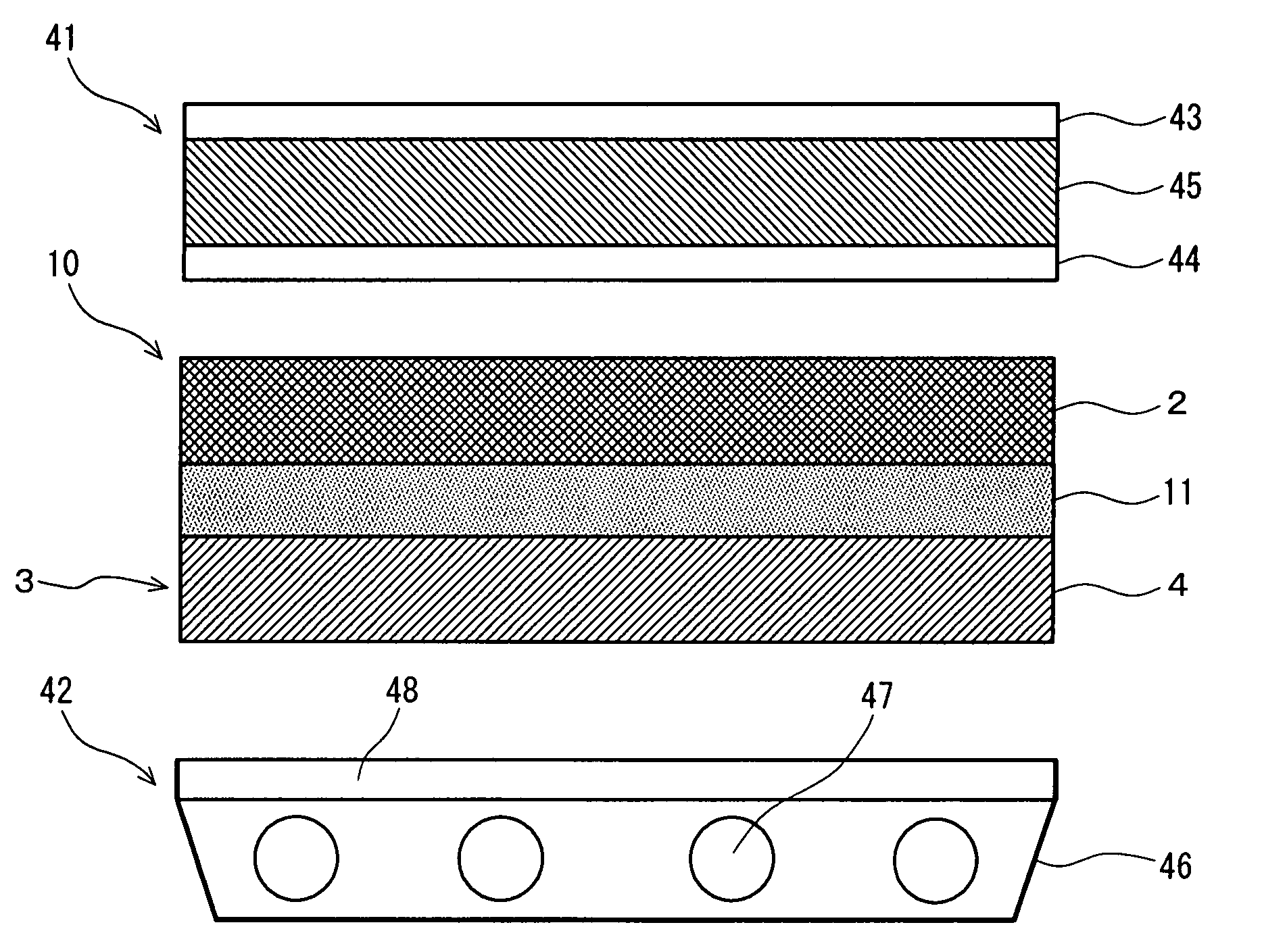
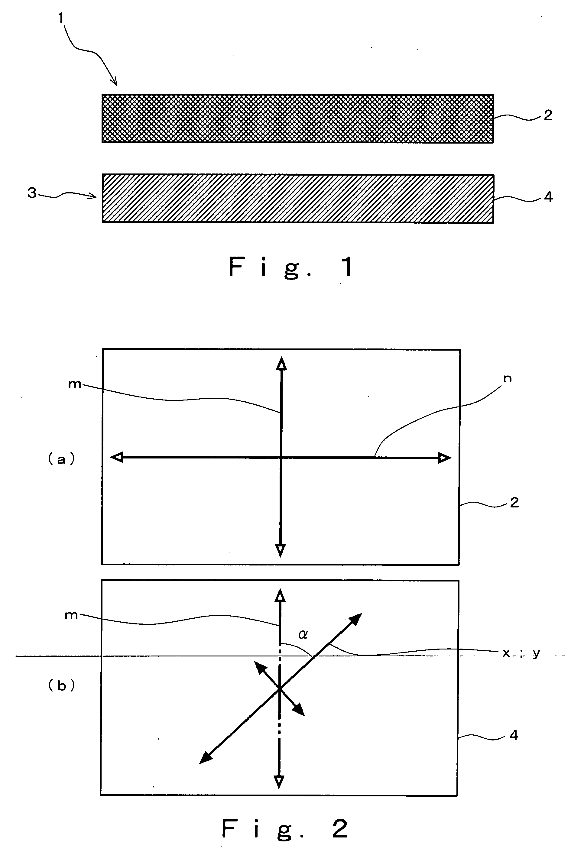
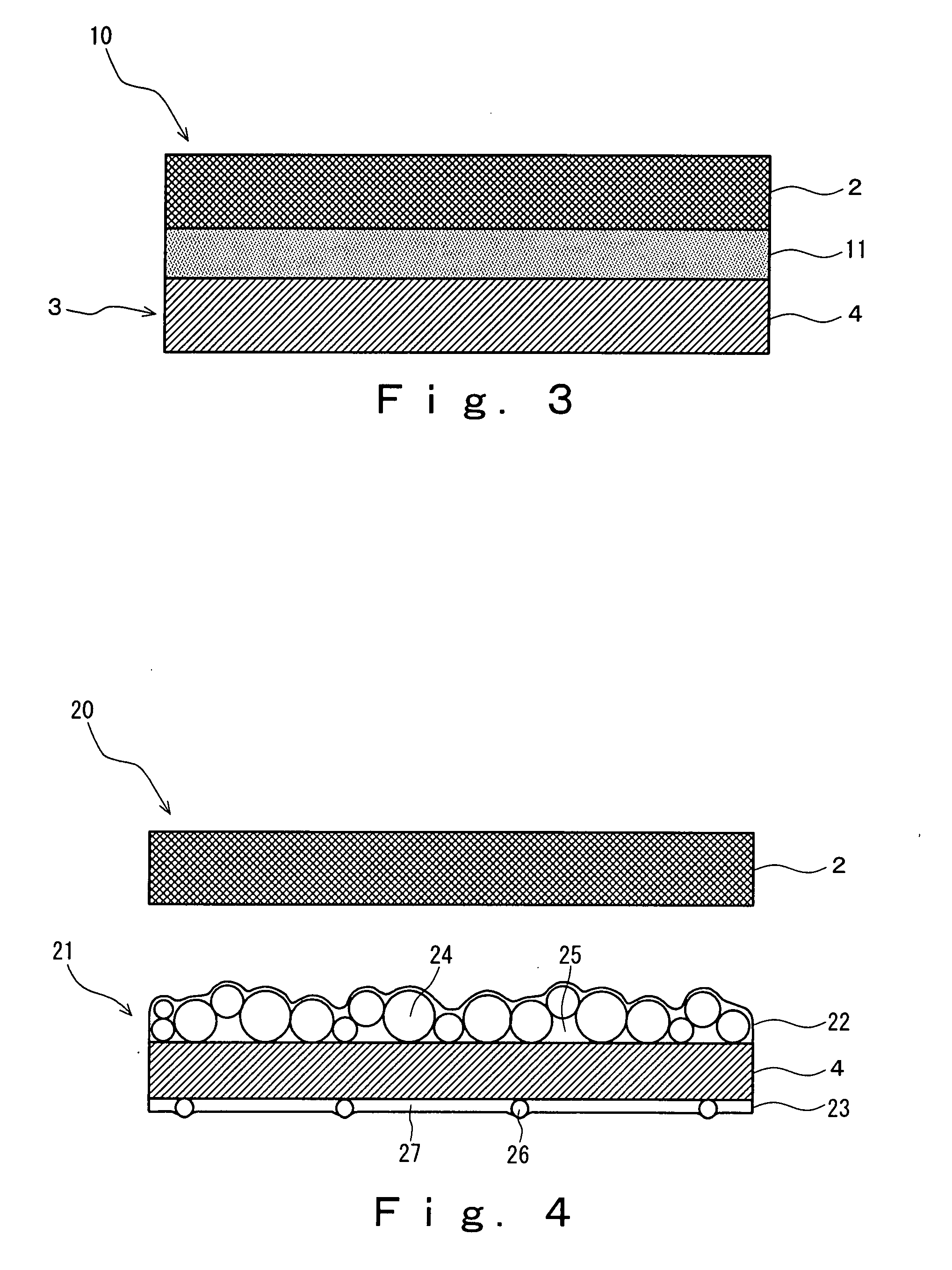
An object of the present invention is to provide an optical unit and a backlight unit which can markedly enhance utilization efficiency of rays of light and dramatically increase luminance, and which are suited for immediate beneath type liquid crystal display modules and the like. The optical unit of the present invention is a rectangular layered structural member having a reflection polarizing plate, an optical sheet superposed on the back face side of the reflection polarizing plate, and a transparent media layer filled between the reflection polarizing plate and the optical sheet. This optical sheet includes a resin substrate film having an optical anisotropy, and the absolute value of the angle of the crystal orientation of the substrate film with respect to the transmission axial orientation of the reflection polarizing plate is π / 8 or greater and 3π / 8 or less. The retardation value of the substrate film is preferably 70 nm or greater and 320 nm or less. The optical sheet preferably has an optical layer laminated on one face of the substrate film. The liquid crystal display module of the present invention has a liquid crystal display element, the optical unit, and an immediate beneath type backlight.

Description

BACKGROUND OF THE INVENTION[0001]1. Field of Invention[0002]The present invention relates to optical units capable of markedly enhancing utilization efficiency of rays of light and improving luminance, and liquid crystal display modules using the same.[0003]2. Description of the Related Art[0004]Liquid crystal display (LCD) modules have been frequently used as a flat panel display through utilizing features such as thinness, lightness in weight, low level of electric power consumption and the like, and applications thereof have been increasing year by year as display devices for information such as mobile phones, personal digital assistances (PDA), personal computers and televisions. In recent years, properties demanded for liquid crystal display modules vary depending on their applications, but may include brightness (high luminance), visibility (widening of viewing angle), energy saving, thin and light modeling capability and the like. In particular, high luminance has been strong...

Claims


Application Information

Patent Timeline
IPC IPC(8): G02B5/30G02F1/1335
CPCG02F1/133536G02F2202/40G02B6/0056G02F1/13362G02B5/30G02F1/1335G02F1/13363
Inventor HARADA, KENICHI
Owner KEIWA INCORPORATED
Learn More