System and Method for Filtering Packets in a Switching Environment

a switching environment and packet filtering technology, applied in the field of communication systems, can solve the problems that traditional switches do not provide the scalability and switching speed typically needed, and achieve the effects of reducing latency, efficient use, and reducing the number of packets

Inactive Publication Date: 2008-05-29
FUJITSU LTD
View PDF24 Cites 28 Cited by
  • Summary
  • Abstract
  • Description
  • Claims
  • Application Information

AI Technical Summary

Benefits of technology

[0003]Particular embodiments of the present invention may reduce or eliminate disadvantages and problems traditionally associated with shared memory resources in a switching environment.
[0005]Particular embodiments of the present invention provide one or more advantages. In particular embodiments, a switch may filter short packets and reallocate the memory resources allocated to the short packets for more efficient use of these resources. In addition, particular embodiments may filter packets more efficiently, thereby reducing latency and increasing the throughput of a switch core. Particular embodiments may also reduce latency by using the switch's drop queue more efficiently. Certain embodiments provide all, some, or none of these technical advantages, and certain embodiments provide one or more other technical advantages readily apparent to those skilled in the art from the figures, descriptions, and claims included herein.

Problems solved by technology

Traditional switches do not provide the scalability and switching speed typically needed to support these interconnects.

Method used


Image

  • System and Method for Filtering Packets in a Switching Environment
  • System and Method for Filtering Packets in a Switching Environment
  • System and Method for Filtering Packets in a Switching Environment

Examples


Embodiment Construction

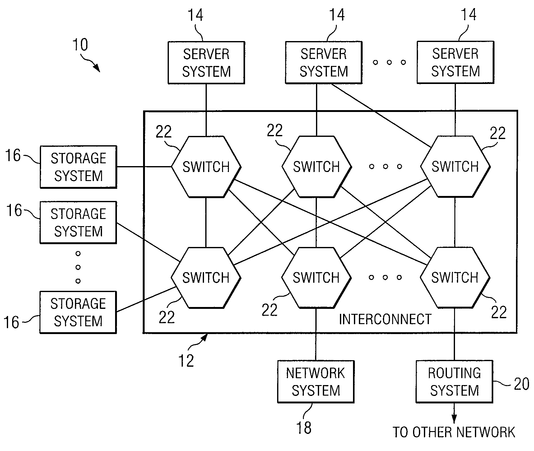
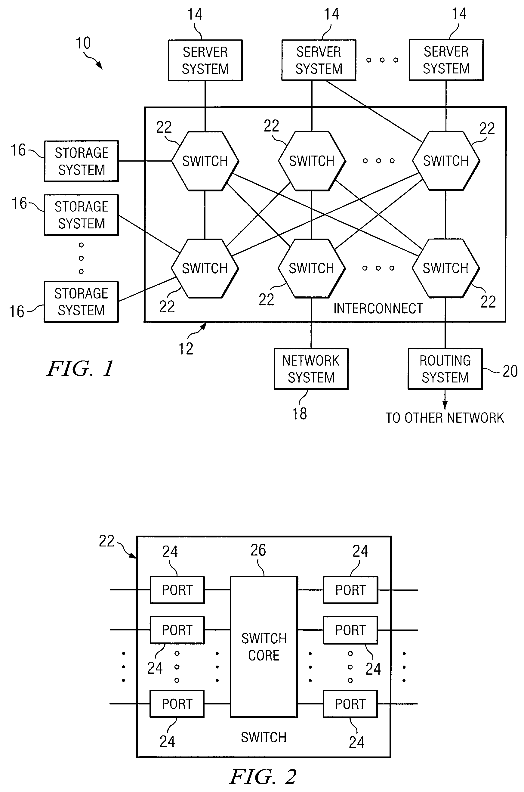
[0014]FIG. 1 illustrates an example system area network 10 that includes a serial or other interconnect 12 supporting communication among one or more server systems 14; one or more storage systems 16; one or more network systems 18; and one or more routing systems 20 coupling interconnect 12 to one or more other networks, which include one or more local area networks (LANs), wide area networks (WANs), or other networks. Server systems 14 each include one or more central processing units (CPUs) and one or more memory units. Storage systems 16 each include one or more channel adaptors, one or more disk adaptors, and one or more CPU modules. Interconnect 12 includes one or more switches 22, which, in particular embodiments, include Ethernet switches, as described more fully below. The components of system area network 10 are coupled to each other using one or more links, each of which includes one or more computer buses, local area networks (LANs), metropolitan area networks (MANs), wi...


PUM


Abstract

In particular embodiments of the present invention, a method for filtering packets in a switching environment is provided. In particular embodiments, the method includes receiving a packet at an input port of a switch, the switch comprising a memory and one or more output ports. The method also includes storing at least a portion of the packet in the memory and determining one or more output ports from which the packet is to be communicated from the switch. The method further includes, after beginning to determine one or more output ports from which the packet is to be communicated from the switch, determining whether the packet is an illegal packet. The method also includes, if the packet is an illegal packet, dropping the packet from the memory, and if the packet is a legal packet, communicating the packet from the determined one or more output ports.

Description

TECHNICAL FIELD OF THE INVENTION[0001]This invention relates generally to communication systems and more particularly to filtering packets in a switching environment.BACKGROUND OF THE INVENTION[0002]High-speed serial interconnects have become more common in communications environments, and, as a result, the role that switches play in these environments has become more important. Traditional switches do not provide the scalability and switching speed typically needed to support these interconnects.SUMMARY OF THE INVENTION[0003]Particular embodiments of the present invention may reduce or eliminate disadvantages and problems traditionally associated with shared memory resources in a switching environment.[0004]In particular embodiments of the present invention, a method for filtering packets in a switching environment is provided. In particular embodiments, the method includes receiving a packet at an input port of a switch, the switch comprising a memory and one or more output ports....

Claims


Application Information

Patent Timeline
Patent Type & Authority Applications(United States)
IPC IPC(8): H04L12/56
CPCH04L49/251H04L49/254H04L49/602H04L49/358H04L49/555H04L49/35
Inventor MIYOSHI, TAKASHINAKAGAWA, YUKIHIROSHIMIZU, TAKESHI
Owner FUJITSU LTD
Why Eureka
Try Eureka