Method and system for efficient rapid loss detection in a bonding system

Inactive Publication Date: 2008-06-05
AVAGO TECH WIRELESS IP SINGAPORE PTE
View PDF20 Cites 7 Cited by
  • Summary
  • Abstract
  • Description
  • Claims
  • Application Information

AI Technical Summary

Problems solved by technology

The wait for a lost packet is a long delay, such as twenty milliseconds or longer.
This delay causes further problems with processing of the resequenced data because downstream processing equipment must adapt to variable and excessive delays in data delivery.

Method used


Image

  • Method and system for efficient rapid loss detection in a bonding system
  • Method and system for efficient rapid loss detection in a bonding system
  • Method and system for efficient rapid loss detection in a bonding system

Examples


Embodiment Construction

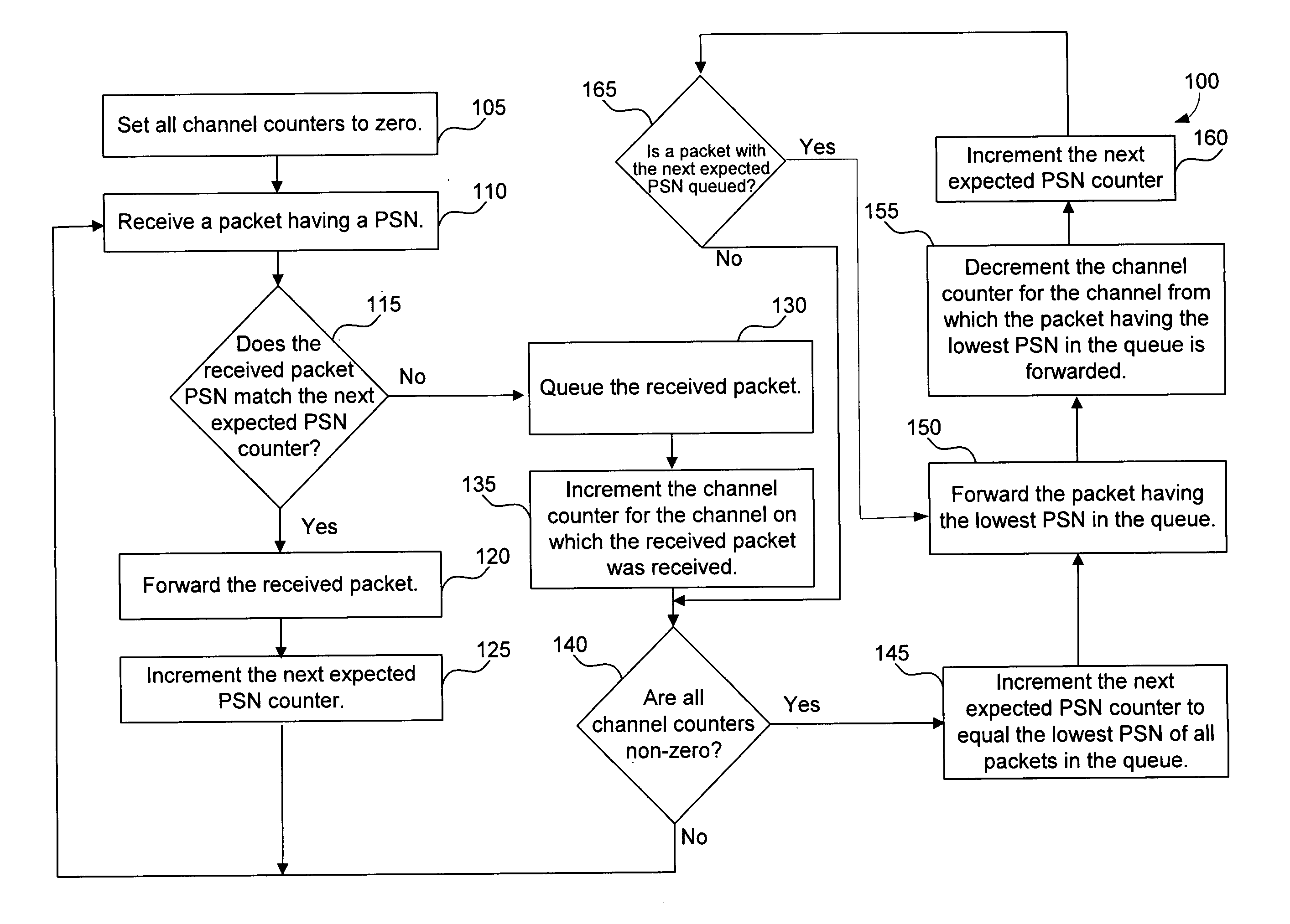
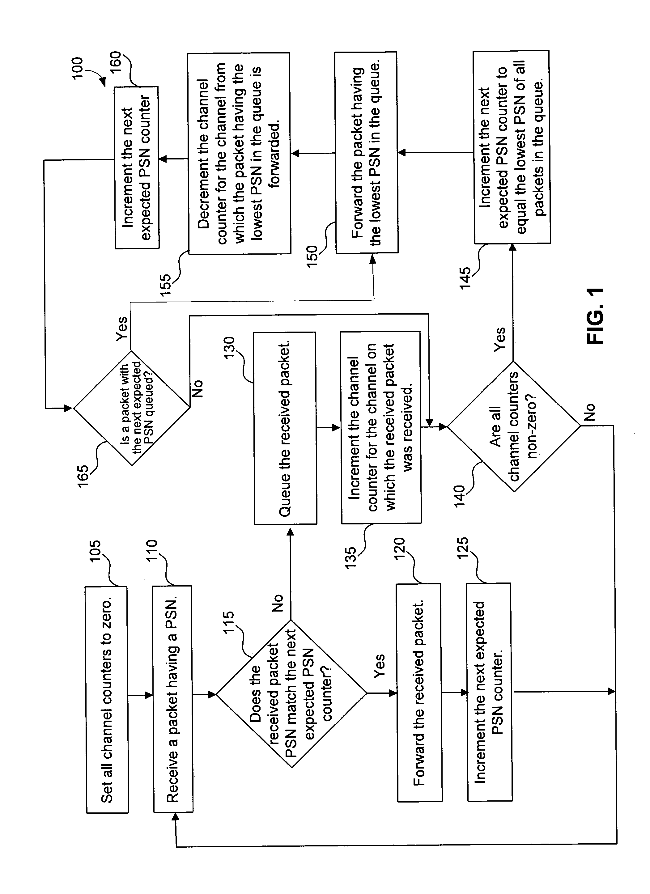
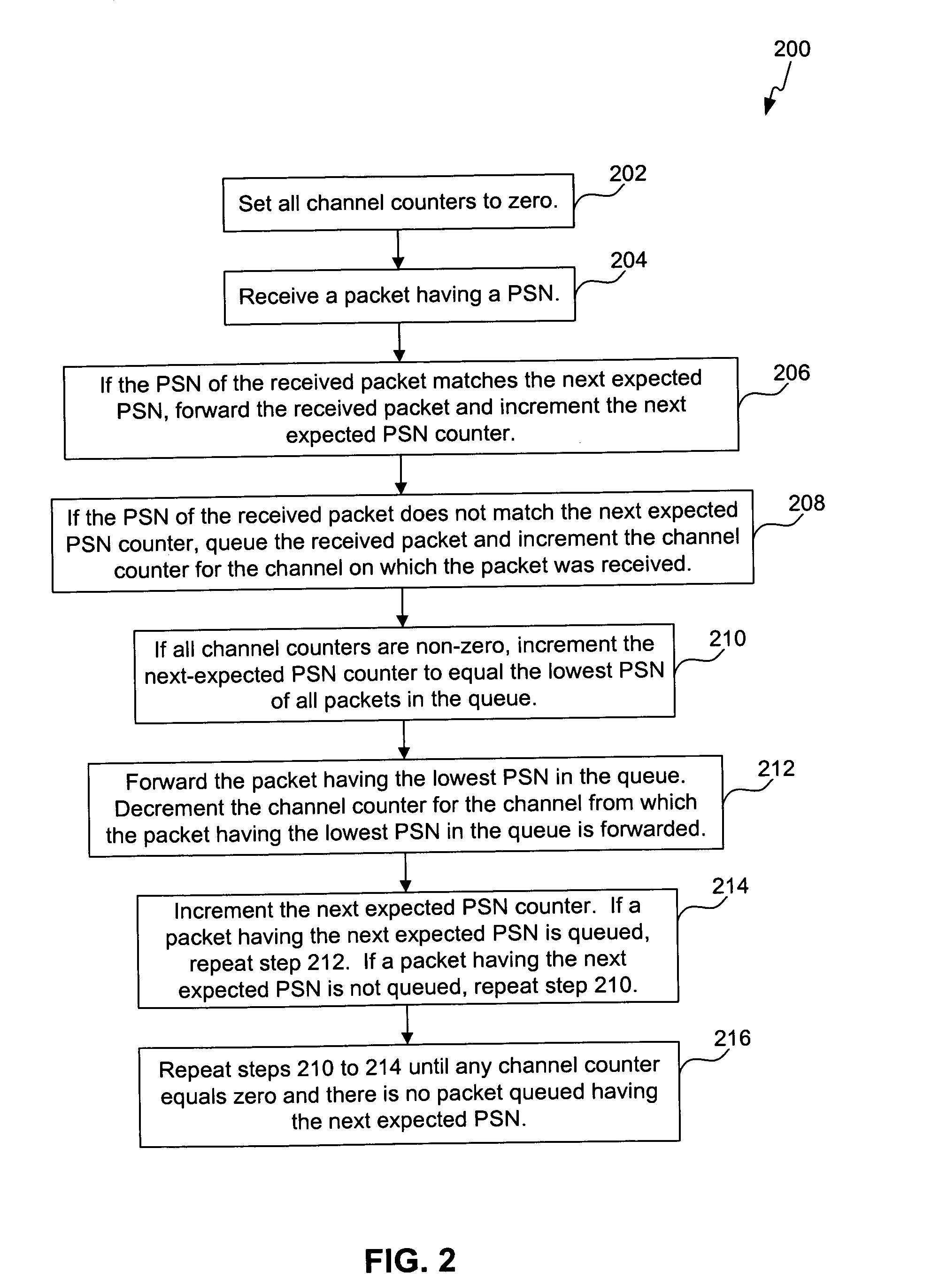
[0015]As introduced above, various embodiments of the invention involve an apparatus, method, and computer program for efficient rapid loss detection in a bonding system. FIGS. 1-6, described below, illustrate this approach. Examples of the invention reduce a receiver delay and reduce receiver hardware requirements by rapidly and efficiently detecting lost data.

[0016]This specification discloses one or more embodiments that incorporate the features of this invention. The disclosed embodiment(s) merely exemplify the invention. The scope of the invention is not limited to the disclosed embodiment(s). The invention is defined by the claims.

[0017]The embodiment(s) described and references in the specification to “one embodiment,”“an embodiment,”“an example embodiment,” etc., indicate that the embodiment(s) described may include a particular feature, structure, or characteristic. However, every embodiment may not necessarily include the particular feature, structure, or characteristic. M...


PUM


Abstract

An apparatus, method, and computer program for efficient rapid loss detection in a channel bonding system. A received packet having a packet sequence number (PSN) not equal to a next expected PSN is queued. A channel counter for a first channel on which the received packet was received is incremented. If all channel counters are non-zero, increment the next expected PSN to equal a lowest queued packet PSN. Forward the queued packet with the lowest queued packet PSN. Decrement a channel counter for a second channel from which the lowest PSN packet is forwarded.

Description

FIELD OF THE INVENTION[0001]The present invention is generally directed to communication systems. More particularly, the invention relates to channel bonding.BACKGROUND OF THE INVENTION[0002]Channel bonding is a process of communicating information through multiple independent communication channels. The multiple channels are treated as a single virtual channel having greater bandwidth than any individual constituent channel. In one method of channel bonding, a transmitter breaks a data stream into multiple packets of data. The transmitter distributes the packets among the each of the individual channels. The packets are tagged with a sequence number by the transmitter so that the receiver may resequence the packets to reproduce the data stream in the proper order.[0003]The receiver queues in memory received packets that are not yet resequenced. When a packet is lost during transmission, for example due to an error, the receiver awaits arrival of the wayward packet. While waiting, t...

Claims


Application Information

Patent Timeline
IPC IPC(8): H04L12/56
CPCH04L45/245H04L47/34H04L47/10
Inventor PULLEN, DAVID MICHAEL
Owner AVAGO TECH WIRELESS IP SINGAPORE PTE
Why Eureka
Try Eureka