
Installation effort deep foudnation method

a deep foudnation and installation effort technology, applied in foundation engineering, bulkheads/piles, construction, etc., can solve the problems of excessive grout or concrete, excessive quantities of softer soil, and high cost of spoilage disposal

Inactive Publication Date: 2008-06-05
NESMITH WILLIE M +1
View PDF32 Cites 26 Cited by
  • Summary
  • Abstract
  • Description
  • Claims
  • Application Information

AI Technical Summary

Benefits of technology

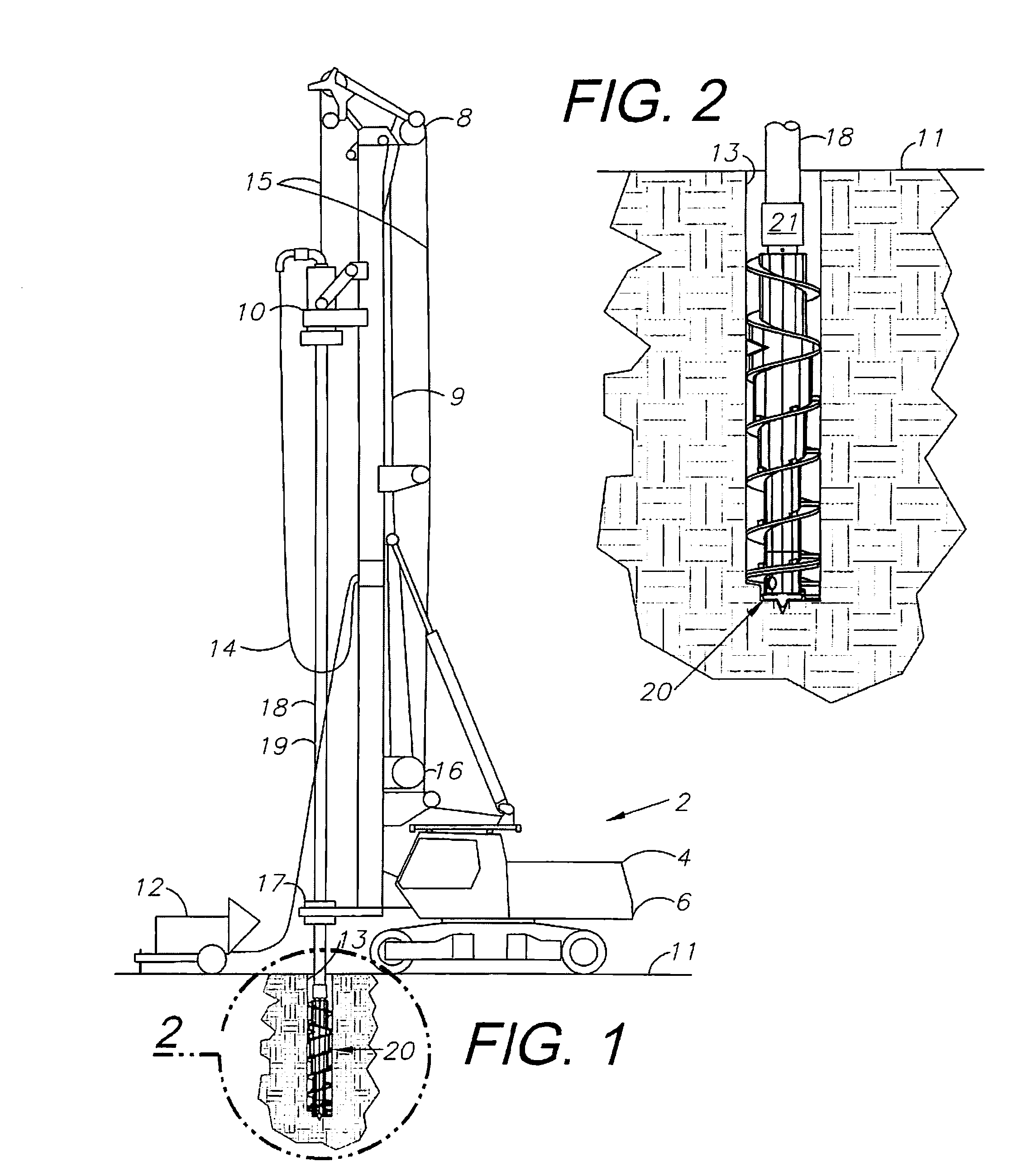
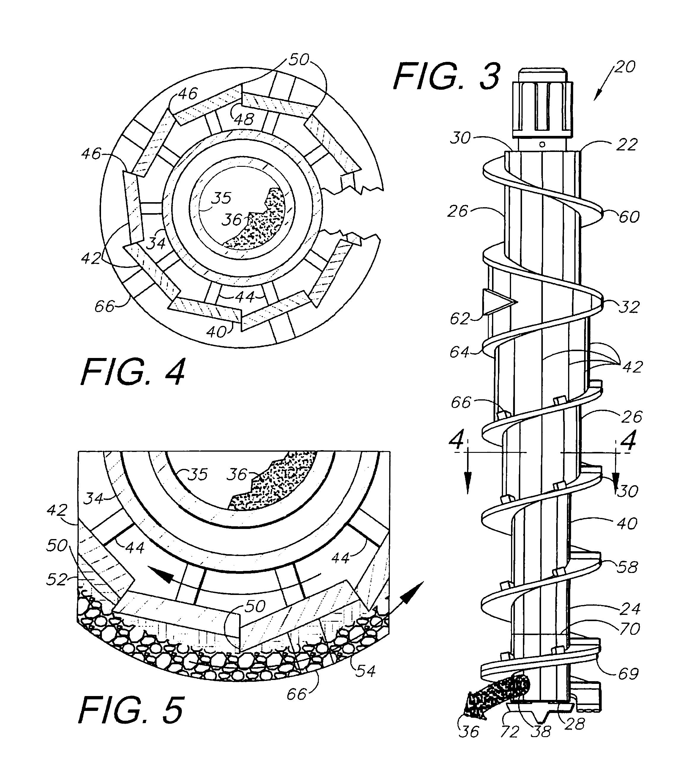
[0015]In the practice of an aspect of the present invention, a full displacement system is provided for forming a drilled displacement (DD) foundation pile. The system includes a rig adapted for hoisting and rotating an auger for drilling a subsurface borehole. The auger includes an auger bit with bidirectional flighting and a tapered stem, which cooperate to laterally displace and compact soil on the borehole periphery. The auger bit includes anti-wear protrusions, comprising stepped edges of the stem plates and blocks extending transversely across the flighting upper faces. The protrusions trap soil in protective positions on the stem and flighting for protecting same from wear. Another anti-wear feature comprises a double layer of flighting at the auger bi...

Problems solved by technology

Spoilage disposal can be particularly expensive and problematical when hazardous wastes are encountered in the subsurface soil being drilled, for example in environmental remediation projects and on project sites containing buried hazardous wastes.
Another disadvantage associated with conventional, full-flight augers relates to over-excavation whereby excessive quantities of softer soil are extracted from certain portions of boreholes.
The resulting over-excavated boreholes often have hourglass-shaped configurations with enlarged portions, which tend to require excessive quantities of grout or concrete as compared to cylindrical, straight-walled boreholes.
Such extra material can be relatively expensive, particularly when multiple and relatively deep boreholes are affected.
Costs associated with bit wear and replacement tend to be relatively high.
However, the specific site stratigraphy may be more complex and may include a transitional increase in strength with depth.

Method used


Image

  • Installation effort deep foudnation method
  • Installation effort deep foudnation method
  • Installation effort deep foudnation method

Examples


Embodiment Construction

I. Introduction and Environment

[0029]As required, detailed embodiments of the present invention are disclosed herein; however, it is to be understood that the disclosed embodiments are merely exemplary of the invention, which may be embodied in various forms. Therefore, specific structural and functional details disclosed herein are not to be interpreted as limiting but merely as a basis for the claims and as a representative basis for teaching one skilled in the art to variously employ the present invention in virtually any appropriately detailed structure.

[0030]Certain terminology will be used in the following description for convenience in reference only and will not be limiting. For example, up, down, front, back, right and left refer to the invention as oriented in the view being referred to. The words “inwardly” and “outwardly” refer to directions toward and away from, respectively, the geometric center of the embodiment being described and designated parts thereof. Said termi...


PUM


Abstract

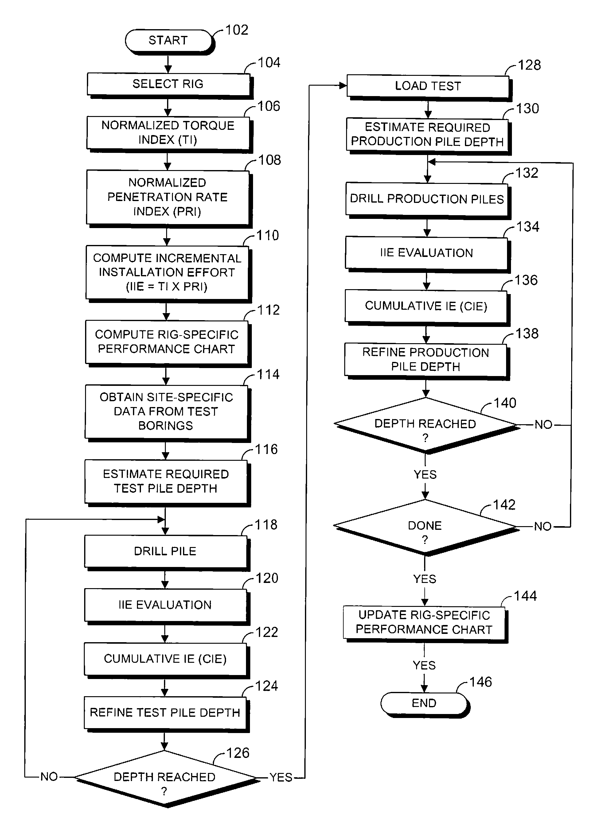
An auger bit is provided for a foundation pile system including a drilling rig adapted for mounting and rotating a grout pipe connected to the auger bit to form an auger. The auger bit includes a stem with lower and upper sections, which taper towards a transition whereat the stem has a maximum diameter. A pile foundation forming method includes the steps of providing a drilling rig, forming an auger with a grout pipe coupled to an auger bit, rotating the auger with the rig, forming a borehole with laterally displaced soil, pumping pressurized grout through the auger and into the borehole, placing a reinforcing cage in the wet grout and curing same. Another aspect of the invention involves correlating installation effort (IE) based on rig-specific performance charts with ultimate pile capacity (Qult).

Description

CROSS-REFERENCE TO RELATED APPLICATION[0001]This application is a continuation-in-part of and claims the benefit of U.S. patent application Ser. No. 11 / 696,054 filed Apr. 3, 2007, which is a continuation of and claims the benefit of U.S. patent application Ser. No. 10 / 890,061, filed Jul. 13, 2004, now U.S. Pat. No. 7,198,434, issued Apr. 3, 2007, which is incorporated herein by reference.BACKGROUND OF THE INVENTION[0002]1. Field of the Invention[0003]The present invention relates generally to deep pile foundations, and in particular to a method of interactively determining a pile depth, i.e. “toe level” necessary to meet a design load capacity criterium.[0004]2. Description of the Related Art[0005]In the field of foundation construction, pile-type foundation systems are commonly used to support a wide variety of structures. Typical structural applications include commercial buildings, institutional buildings, industrial facilities, power plants, transportation and other structures i...

Claims


Application Information

Patent Timeline
IPC IPC(8): E02D5/56
CPCE02D5/36E02D7/22E02D5/56
Inventor NESMITH, WILLIE M.BLUM, KENNETH J.
Owner NESMITH WILLIE M
Learn More