Applicator for tampons

a technology of tampons and tampons, applied in the field of tampons, can solve the problems of damage to the body, adverse effects on the environment, and the value becomes difficult to increase the contact resistance to the body

Inactive Publication Date: 2002-08-13
UNI CHARM CORP
View PDF6 Cites 57 Cited by
  • Summary
  • Abstract
  • Description
  • Claims
  • Application Information

AI Technical Summary

Problems solved by technology

If the valves are opened, the leading portion of the outer cylinder may give an unnecessary resistance to the human body or may damage the body when the leading portion of the outer cylinder is inserted into the vaginal cavity.
With the increased thickness, however, the amount of resin to be employed increases to cause a pro

Method used


Image

  • Applicator for tampons
  • Applicator for tampons
  • Applicator for tampons

Examples


example 3

, Example 3, and Comparative Example 1 and Comparative Example 2, as shown in the following Table 1.

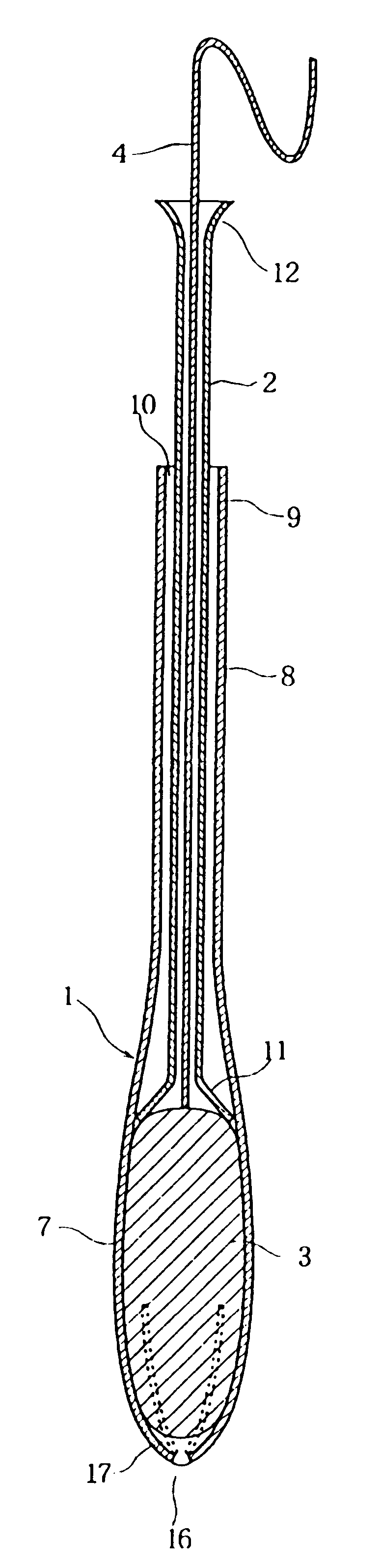
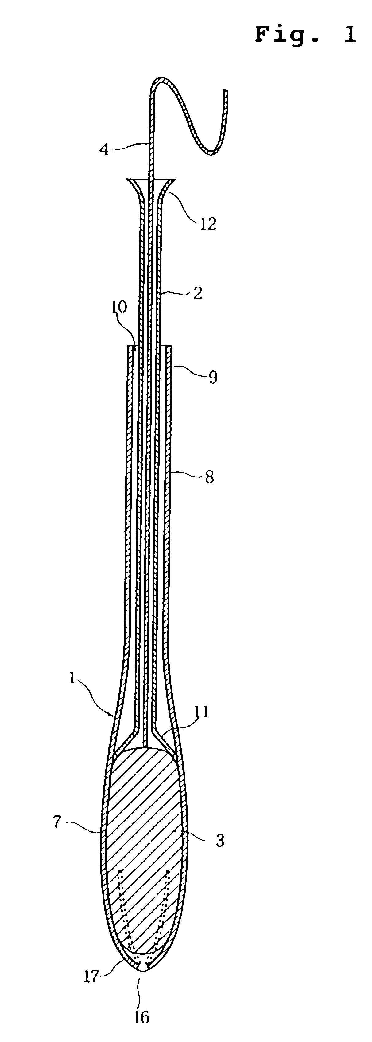
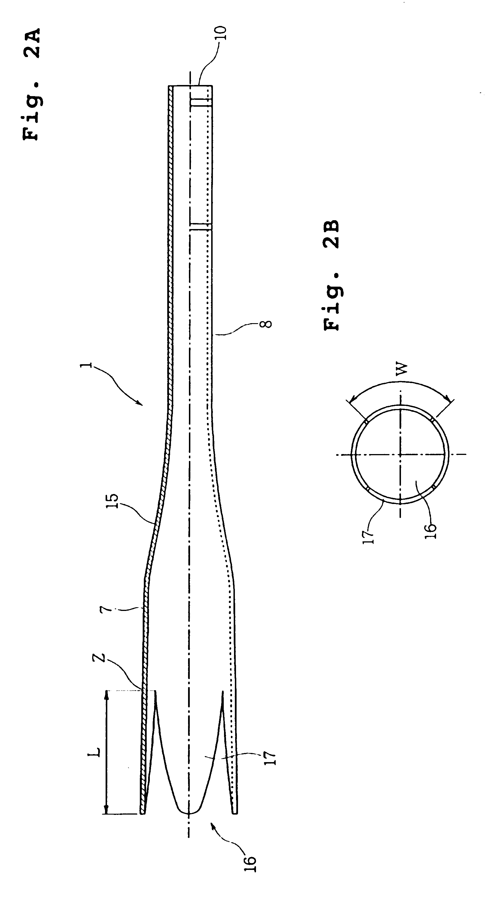
The employed resin was LDPE (i.e., low density polyethylene) having a density of 0.92 g / cm.sup.3 and an MFR (i.e., melt flow rate) of 48. This resin was injection-molded to form the outer cylinder 1 having a shape similar to that shown in FIG. 2A.

Evaluations

Injection-Moldability:

The outer cylinder having a shape similar to that shown in FIG. 2A was injection-molded, and the shape of the leading portions of the valves were observed. The outer cylinders were judged as defective moldings, as indicated by "X", if their leading ends were cut out or burred.

Opening of Valves at Leading End:

The injection-molded outer cylinder was heated at its leading end with the die so that the valves were curved to form the curved face portion, and was left for one week in the oven of 40.degree. C. The opening of the leading ends of the valves was observed. The valves were judged to be defective, as indica...


PUM


Abstract

Provided is an applicator for a tampon including an outer cylinder having a large diameter portion for fitting a tampon therein, a small diameter portion provided on the side of a rear end of the outer cylinder and having a smaller diameter than that of the large diameter portion; and a plurality of valves provided on the side of a leading end of the outer cylinder. The valves are converged to have a curved face portion to be diametrically gradually reduced toward the leading end of the outer cylinder, and a push-out member is movably inserted into the small diameter portion of the outer cylinder. A ratio A/B is at most 0.8, when an inflection point for the boundary between the maximum diameter portion of the large diameter portion and the curved face portion is designated by Z, a radius of the outer face at the inflection point Z is designated by A, and the axial length from the inflection point Z to the leading end of the curved face portion is designated by B. A ratio L/W is within a range of 1.0 to 2.0, when the width size of root ends of the valves is designated by W and the length of the valves is designated by L.

Description

1. Field of the InventionThe present invention relates to an applicator for a tampon to be employed when a sanitary tampon is to be inserted into a human body.2. Description of the Related ArtThe applicator for the sanitary tampon is constructed to include an outer cylinder for fitting the tampon therein, and an inner cylinder inserted into the outer cylinder and protruding rearwardly from the rear end of the outer cylinder. A take-out cord extending from the tampon, is led out of the outer cylinder through the inner cylinder and protruded rearwardly from a rear end of the inner cylinder.When the tampon is to be employed, the outer cylinder is inserted into a vaginal cavity, and the inner cylinder is pushed to push the tampon out of the outer cylinder. Then, the tampon is inserted into the vaginal cavity while expanding a number of deformable valves at the leading end of the outer cylinder.Some of the existing applicators are formed to have an outer cylinder and an inner cylinder wh...

Claims


Application Information

Patent Timeline
IPC IPC(8): A61F13/20A61F13/26A61F13/32
CPCA61F13/26A61F13/20
Inventor WADA, MITSUHIROSUGA, AYAMI
Owner UNI CHARM CORP
Why Eureka
Try Eureka