Wire with terminal

a terminal and wire technology, applied in the direction of permanent deformation connection, line/current collector details, coupling contact members, etc., can solve the problems of thin wire core not having enough strength against external force applied to thin wire, etc., to improve electrical connection reliability

Active Publication Date: 2020-07-07
AUTONETWORKS TECH LTD +2
View PDF8 Cites 0 Cited by
  • Summary
  • Abstract
  • Description
  • Claims
  • Application Information

AI Technical Summary

Benefits of technology

[0006]The tips of the wire barrels are sandwiched by the first, second and third strands according to the above configuration. Thus, the opening of the wire barrels can be suppressed, and electrical connection reliability between the wire and the terminal can be improved.
[0016]According to the invention, it is possible to improve electrical connection reliability between a wire and a terminal.

Problems solved by technology

Recently, wires have been required to be thinner, and a core may not have sufficient strength against an external force applied to a thin wire.

Method used


Image

  • Wire with terminal
  • Wire with terminal
  • Wire with terminal

Examples


Embodiment Construction

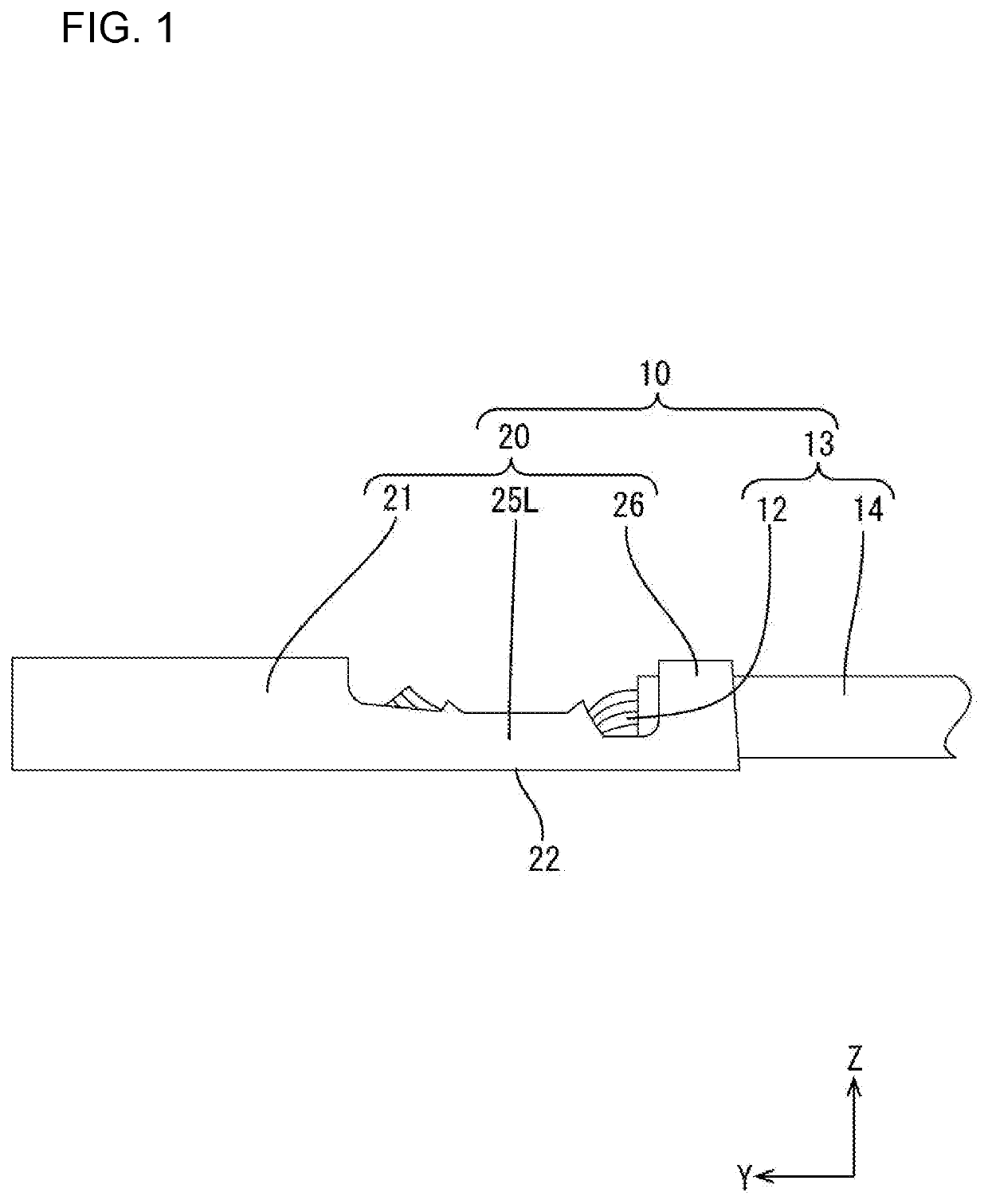
[0024]An embodiment of the invention is described with reference to FIGS. 1 to 7. In this embodiment, a wire with terminal 10 in which a female terminal 20 is connected to an end of a wire 13 is illustrated as shown in FIG. 1. In the following description, a Z direction, a Y direction and an X direction are respectively referred to as an upward direction, a forward direction and a leftward direction. Further, for a plurality of identical members, one member may be denoted by a reference sign and the other member(s) may not be denoted by the reference sign.

[0025](Wire 13)

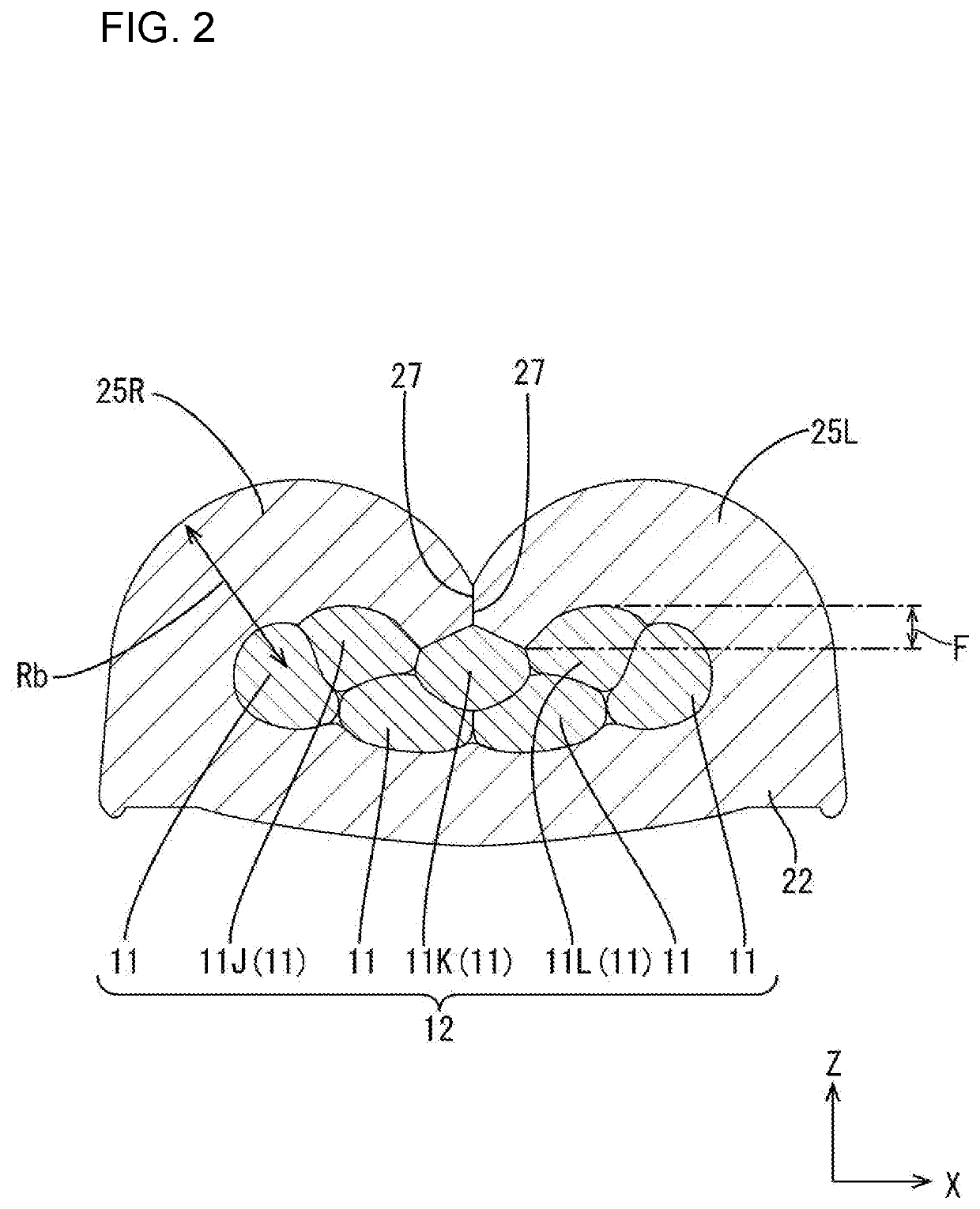
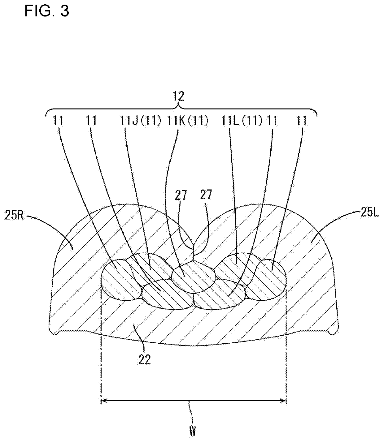
[0026]As shown in FIG. 5, the wire 13 is structured such that the outer periphery of a core 12 is covered by an insulation coating 14 made of synthetic resin. The core 12 includes strands 11 (seven in this embodiment) made of conductive metal. The core 12 is a twisted wire formed by twisting the plurality of strands 11. In the core 12, six peripheral strands 11B are twisted spirally with one center strand 11A as a ce...


PUM


Abstract

A terminal (20) is connected to a core (12) of a wire (13). The terminal (20) includes two wire barrels (25L, 25R) extending from a bottom portion (22) on which the core (12) is placed. The wire barrels (25L, 25R) are crimped to wind around the core (12). The core (12) includes strands (11) made of metal having a larger tensile strength than metal of the female terminal (20). At least first, second and third strands (11J, 11K) and (11L) are disposed side by side in a direction intersecting an extending direction of the core (20) inside the wire barrels (25L, 25R). A tip of the wire barrels (25L, 25R) is inserted between the first and second strands (11J, 11K) and a tip of the other of the pair of wire barrels (25L, 25R) is inserted between the second and third strands (11K, 11L).

Description

BACKGROUNDField of the Invention[0001]This specification relates to a wire with terminal in which a terminal fitting is connected to an end part of a wire.Related Art[0002]Japanese Unexamined Patent Publication No. 2009-117039 discloses a wire with terminal in which a terminal is connected to a core of a wire. The core includes strands made of conductive metal. The terminal includes a bottom portion on which the core is placed, and two wire barrels extend from this bottom portion. The wire barrels are crimped to wind around the outer periphery of the core. In this way, the wire and the terminal are connected electrically.[0003]Recently, wires have been required to be thinner, and a core may not have sufficient strength against an external force applied to a thin wire. The strength of strands of the core could be improved to suppress a trouble of the core due to an external force. However, the strength of a metal of the strands could become larger than that of a metal material of the...

Claims


Application Information

Patent Timeline
Patent Type & Authority Patents(United States)
IPC IPC(8): H01R13/02H01R4/18H01R4/62H01R43/048
CPCH01R4/184H01R13/02H01R4/188H01R4/185H01R43/048H01R4/62H01R4/20H01R11/11
Inventor SHIMADA, TAKANOBU
Owner AUTONETWORKS TECH LTD
Why Eureka
Try Eureka