
Battery stack

a battery and stack technology, applied in the field of batteries, can solve the problems of fatigue damage to the welded portion, and achieve the effect of suppressing an opening of the case, improving and increasing the strength of the cas

Active Publication Date: 2018-03-27
TOYOTA JIDOSHA KK
View PDF15 Cites 0 Cited by
  • Summary
  • Abstract
  • Description
  • Claims
  • Application Information

AI Technical Summary

Benefits of technology

The design significantly extends the service life of the battery stack by reducing fatigue-induced deterioration, allowing for repeated cycles of internal pressure increase without failure, meeting a 10-year service life standard when the spacer ratio is within 0.02≤B / C≤0.09.

Problems solved by technology

When such a case is repeatedly inflated and contracted, a welded portion is deteriorated by fatigue.

Method used


Image

  • Battery stack
  • Battery stack
  • Battery stack

Examples


modified embodiment

[0044](Modified Embodiment)

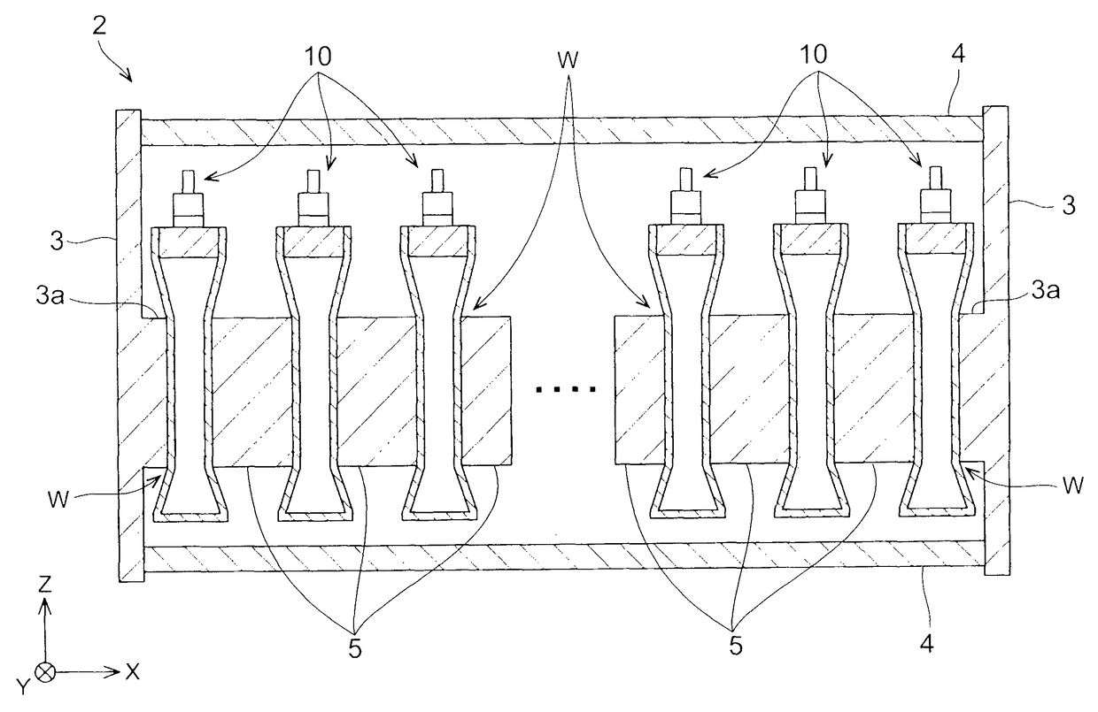
[0045]As described above, the flat surface is not recessed when no load is applied to the battery pack, and it is preferred to apply the load until the flat, surface obtains the specified recess. Although the same effect that is achieved by the above battery pack cannot be obtained, the battery pack that is formed with the recess W from the beginning can also have the improved durability against the deterioration by fatigue in comparison with the conventional battery pack. An example of the battery pack in such an aspect is shown in FIG. 9. A battery pack 110 in FIG. 9 is the same as the battery pack 10 shown in FIG. 6; however, it is different from the battery pack 10 in FIG. 6 in a point that a recess W2 is formed with no application of load. A rectangle indicated by a phantom line (a two-dotted chain line) corresponds to the spacer 5. Thus, a bent portion of the flat surface that is indicated by the reference symbol P6 corresponds to the upper end of th...


PUM

PropertyMeasurementUnit
sizeaaaaaaaaaa
lengthaaaaaaaaaa
lengthaaaaaaaaaa

Abstract

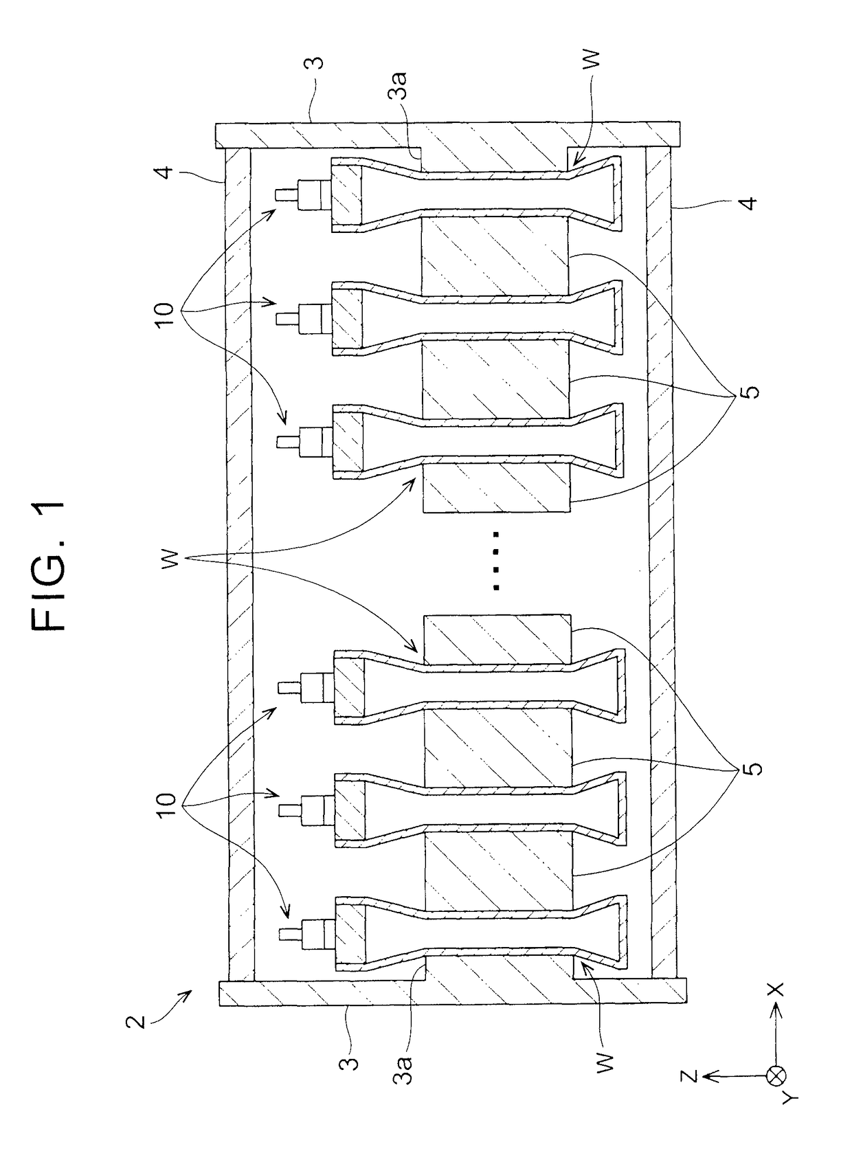
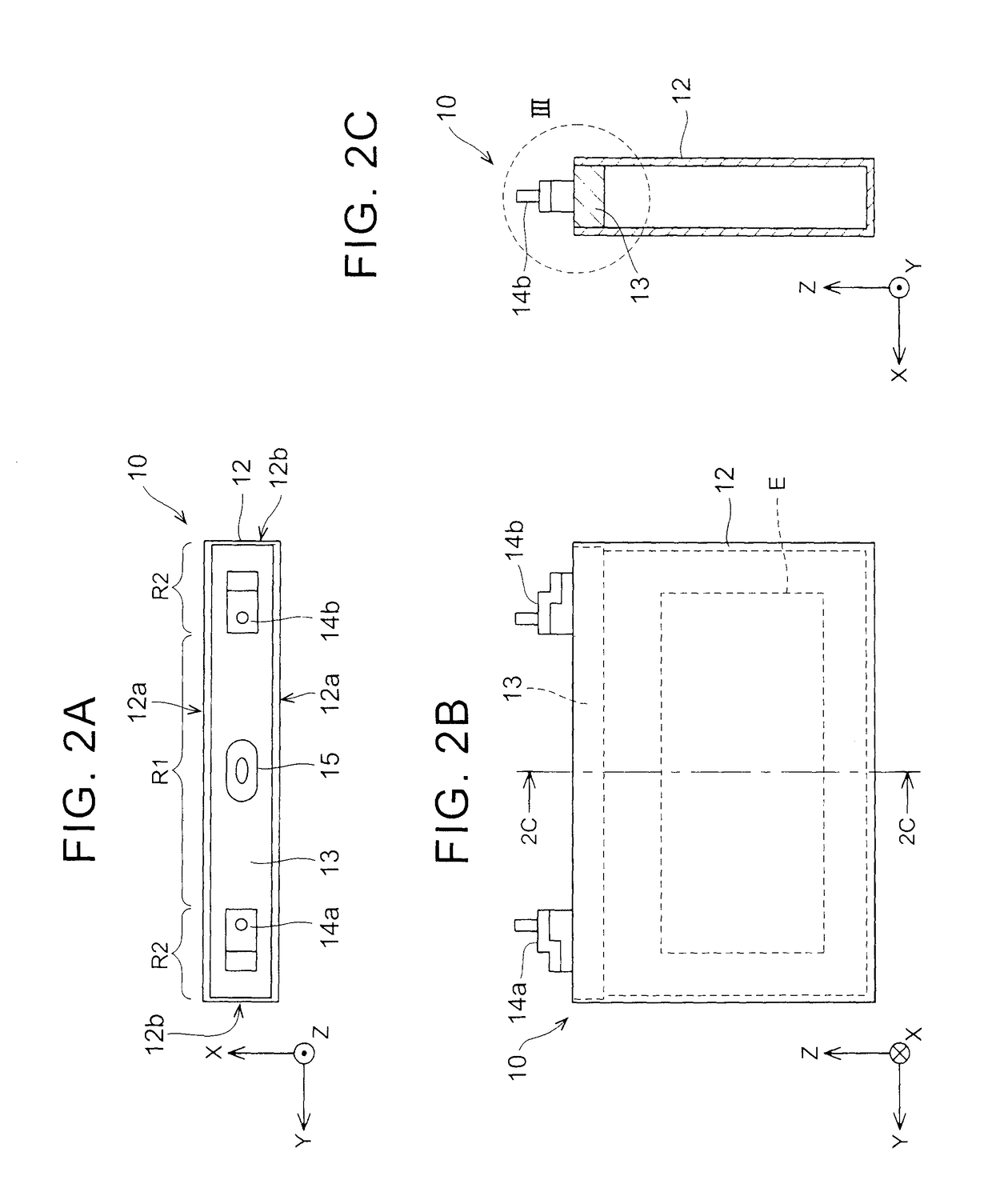
A battery stack includes a plurality of battery packs and a plurality of spacers. The battery pack each has a case and a sealing plate. The sealing plate is fitted to an inner peripheral surface of an opening of the case. Each of the plurality of spacers is arranged at the center of a flat surface on each side of the battery pack, and a contour of a contact region of the spacer with the flat surface is smaller than a contour of the flat surface of the battery pack. The plurality of spacers and the plurality of battery packs are alternately stacked. The plurality of spacers and the plurality of battery packs are applied with a load in a stacking direction. The center of the flat surface of the battery pack is recessed in a shape of a contour of the spacer by the load.

Description

BACKGROUND OF THE INVENTION[0001]1. Field of the Invention[0002]The present invention relates to a battery stack that is configured of a plurality of battery packs. In the battery stack in which the plurality, of battery packs is stacked, the individual battery pack is sometimes referred to as a “battery cell” or simply as a “cell”.[0003]2. Description of Related Art[0004]There is a case where a high-voltage or large-capacity battery is realized by connecting a plurality of battery packs in series or in parallel. Such a battery is referred to as a battery stack. The individual battery pack tends to have a flat shape. Japanese Patent Application Publication No. 2003-242956 (JP 2003-242956 A) discloses a battery stack in which a plurality of flat battery packs is aligned and connected in series.[0005]For the battery pack, a representative example of which is a lithium-ion battery, an electrolyte and a battery main body are housed in a sealed flat case. Since the case is sealed, an int...

Claims


Application Information

Patent Timeline
Patent Type & Authority Patents(United States)
IPC IPC(8): H01M2/08H01M2/02H01M10/04H01M2/04H01M10/34H01M10/0525H01M10/42H01M2/10H01M10/0585H01M50/103H01M50/131H01M50/209H01M50/271H01M50/291
CPCH01M10/0585H01M10/345H01M10/4207H01M2/024H01M2/08H01M2/0217H01M2/0285H01M2/0426H01M2/1061H01M2/1077H01M10/0413H01M10/0468H01M10/0481H01M10/0525H01M2200/20H01M2220/20Y02E60/10H01M50/103H01M50/169H01M50/209Y02P70/50H01M50/131H01M50/291H01M50/271
Inventor SUZUKI, SATOSHI
Owner TOYOTA JIDOSHA KK
Learn More