Wiper for vehicle

一种刮水器、车辆的技术,应用在车辆保养、车辆的清洗、运输和包装等方向,能够解决刮水片小型化困难等问题,达到抑制张开的效果

Active Publication Date: 2014-10-01
DENSO CORP
View PDF9 Cites 0 Cited by
  • Summary
  • Abstract
  • Description
  • Claims
  • Application Information

AI Technical Summary

Problems solved by technology

Therefore, in the connection structure of the support shaft as shown in the above-mentioned Patent Document 2, miniaturization in the height direction of the wiper blade is difficult.

Method used


Image

  • Wiper for vehicle
  • Wiper for vehicle
  • Wiper for vehicle

Examples


Embodiment Construction

[0034] One embodiment of a vehicle wiper will be described below.

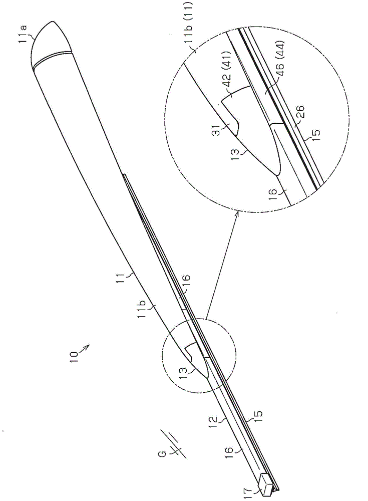
[0035] like figure 1As shown, the vehicle wiper blade 10 of this embodiment is used to wipe off raindrops and the like adhering to the surface (wiping surface G) of the rear glass of the vehicle. The vehicle wiper 10 is composed of a resin wiper arm 11 and a wiper blade 12 which is rotatably connected to the tip end of the wiper arm 11 and is arranged in contact with a wiper surface. on G.

[0036] A base end portion of the wiper arm 11 is connected to an arm head 11 a fixed to a pivot shaft not shown. The wiper arm 11 and the wiper blade 12 move back and forth based on the above-mentioned pivot shaft being rotationally driven by a wiper motor (not shown). Then, wiping on the wiping surface G is performed by the swinging wiper blade 12 . In addition, a spring (not shown) for generating a pressing force for pressing the wiper blade 12 against the wiping surface G is attached to the wiper arm 11 .

[0037] ...


PUM


Abstract

A wiper for a vehicle is provided with: an arm-side connection section (31); a blade-side connection section (41); support shafts (43) which protrude from side walls of the blade-side connection section; and shaft support recesses (32) which are provided in the arm-side connection section and into which the support shafts are fitted in a rotatable manner. The small-diameter sections (43b) of the support shafts have a radial dimension smaller than the diameter of the support shafts. The mounting-dismounting openings (34) of the shaft support recesses have a dimension which is smaller than the diameter of the support shafts and which is greater than the radial dimension of the small-diameter sections. When a wiper blade (12) is located in a mounting-dismounting enabled region, the mounting-dismounting openings and the small-diameter sections of the support shafts match with each other, and the support shafts and the shaft support recesses can be mounted to and dismounted from each other. When the wiper blade is located in a mounting-dismounting disabled region, the mounting-dismounting openings and the small-diameter sections do not match with each other, and the support shafts and the shaft support recesses cannot be mounted to and dismounted from each other. A shape retaining section (33) is located between the pair of the shaft support recesses.

Description

technical field [0001] The present invention relates to a vehicle wiper for wiping a windshield and a back glass of a vehicle. Background technique [0002] In conventional vehicle wipers, the wiper blade is rotatably connected to the top end portion of the wiper arm so that the wiper blade can move following the curvature of the wiper surface. For example, in the vehicle wiper of Patent Document 1, it has such a structure that the connection hole formed through the tip of the wiper arm is rotatably connected to the support formed on the wiper blade through elastic engagement. on axis. However, in such a structure, on the one hand, the connection between the support shaft and the connection hole is elastically engaged, so that the assembly and disassembly of the wiper arm and the wiper blade become easy, and on the other hand, due to the weak connection force between the support shaft and the connection hole. , there is a possibility of unintentional disconnection of the c...

Claims


Application Information

Patent Timeline
Patent Type & Authority Applications(China)
IPC IPC(8): B60S1/34B60S1/38
CPCB60S1/3881B60S2001/409B60S1/4064B60S1/3867B60S1/3863B60S1/3856
Inventor 内山庆多平田圭
Owner DENSO CORP
Why Eureka
Try Eureka