Fuel supply apparatus for internal combustion engine

Inactive Publication Date: 2008-01-10
HONDA MOTOR CO LTD
View PDF13 Cites 0 Cited by
  • Summary
  • Abstract
  • Description
  • Claims
  • Application Information

AI Technical Summary

Benefits of technology

[0007]The present invention was made contemplating the above-described drawback. An object of the present invention is to provide a fuel supply apparatus for an internal combustion engine

Problems solved by technology

There is a problem described below in a case where a common-rail, which is provided with a relief valve which opens when the fuel pressure becomes abnormally high, is used and it takes a long time period for the relief valve to return to the initial closed state once the relief valve opens.
In such state, if the mixed air vanishes, the discharge amount

Method used


Image

  • Fuel supply apparatus for internal combustion engine
  • Fuel supply apparatus for internal combustion engine
  • Fuel supply apparatus for internal combustion engine

Examples


Embodiment Construction

[0015]Preferred embodiments of the present invention will now be described with reference to the drawings.

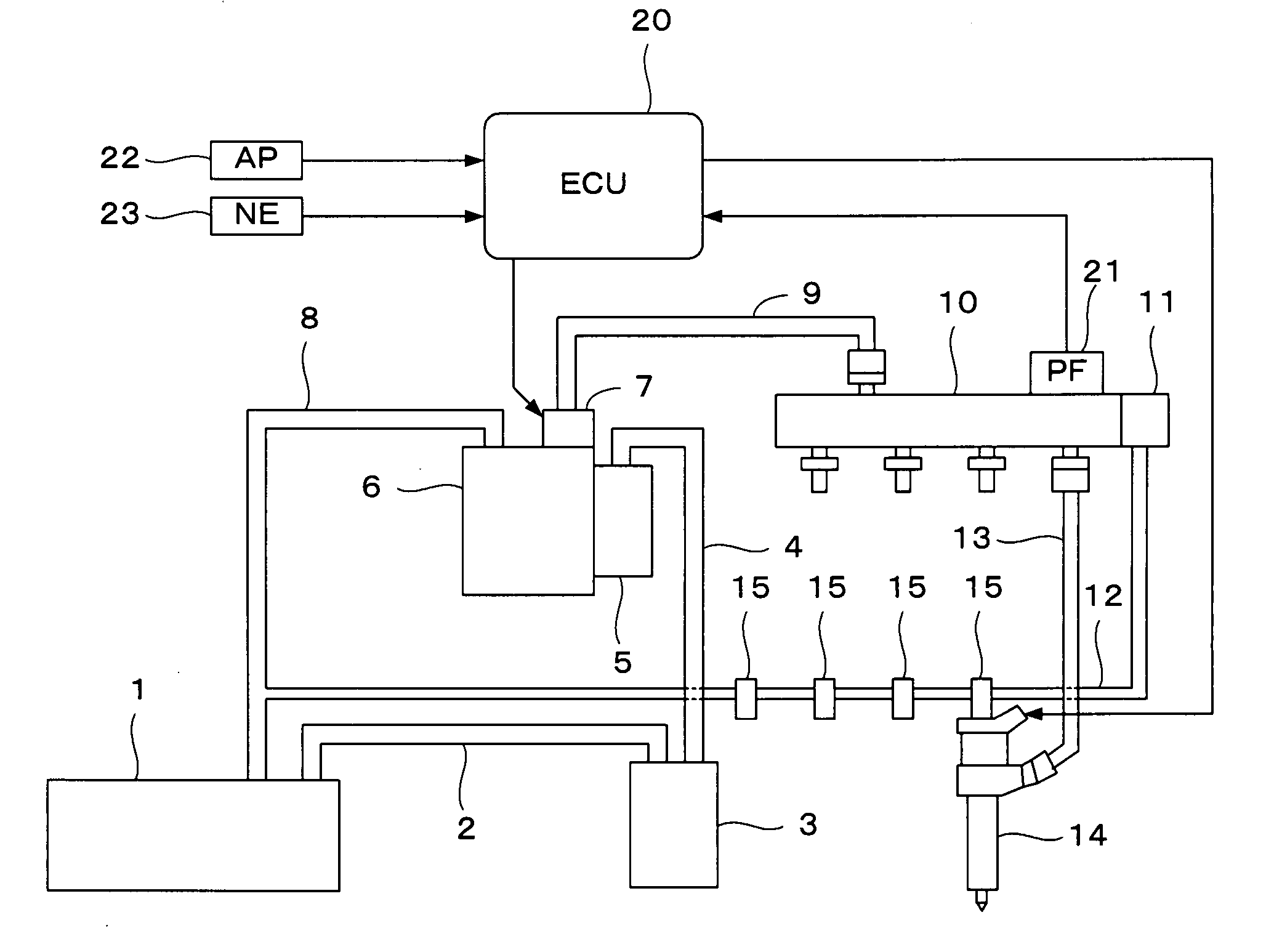
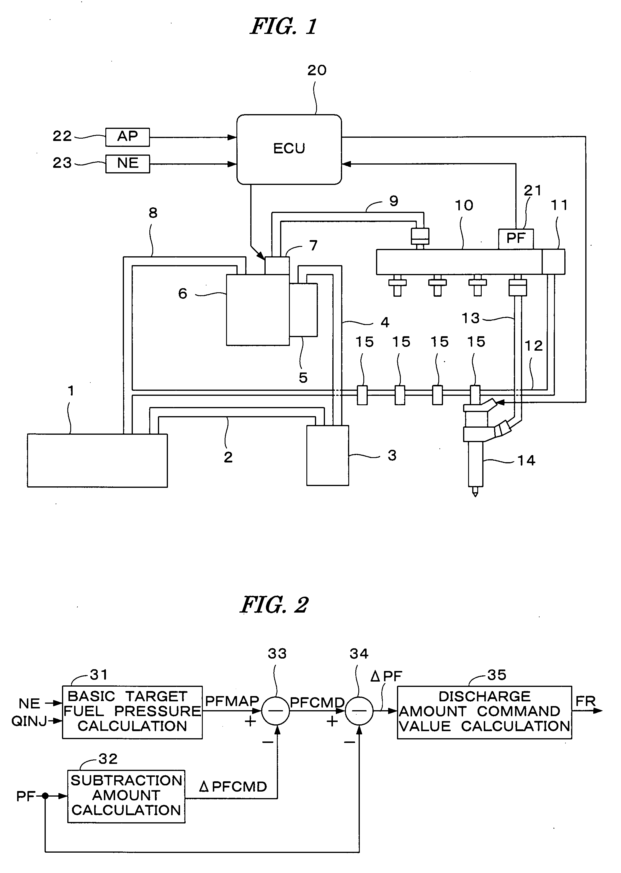
[0016]FIG. 1 is a schematic diagram showing a configuration of a fuel supply apparatus according to one embodiment of the present invention. The fuel supply apparatus supplies fuel to an internal combustion engine (not shown) (hereinafter referred to as “engine”) through a fuel injection valve 14 provided in each combustion chamber of the engine. In this embodiment, the engine is a 4-cylinder engine, but the fuel injection valve 14 is illustrated corresponding to only one cylinder.

[0017]A fuel tank 1 is connected to a strainer 3 through a fuel supply passage 2, and the strainer 3 is connected to a gear pump 5 through a fuel supply passage 4. The gear pump 5 is configured in one body together with a high-pressure pump 6, and the fuel sucked up by the gear pump 5 is supplied to the high-pressure pump 6 and pressurized. The gear pump 5 and the high-pressure pump 6 are driven by the...


PUM


Abstract

A fuel supply apparatus for an internal combustion engine is disclosed. The fuel supply apparatus includes a fuel pump driven by the engine, a pressure accumulating device for retaining the fuel pressurized by the fuel pump, a relief device which opens when a fuel pressure in the pressure accumulating device exceeds a predetermined upper limit pressure. An injection device is connected to the pressure accumulating device and injects fuel into a combustion chamber of the engine. A fuel pressure in the pressure accumulating device is detected. A discharge amount of the fuel pump is controlled so that the detected fuel pressure coincides with a target fuel pressure. The target fuel pressure is reduced when the detected fuel pressure is equal to or greater than a predetermined fuel pressure, to suppress opening of the relief device.

Description

BACKGROUND OF THE INVENTION[0001]1. Field of the Invention[0002]The present invention relates to a fuel supply apparatus for an internal combustion engine, and particularly to a fuel supply apparatus for injecting fuel directly into a combustion chamber of the internal combustion engine.[0003]2. Description of the Related Art[0004]Japanese Patent Laid-open (Kokoku) No. H07-72511 discloses a fuel supply apparatus in which fuel pressurized by a fuel pump is retained in a fuel accumulator (common-rail), and the pressurized fuel is supplied from the fuel accumulator to a fuel injection valve. A technique for rapidly converging a fuel pressure in the fuel accumulator to a target fuel pressure is disclosed. According to this apparatus, a discharge amount of the fuel pump is controlled to the minimum and an electromagnetic valve provided in the fuel accumulator is opened, to rapidly converge the fuel pressure in the fuel accumulator to the target fuel pressure, when the fuel pressure in th...

Claims


Application Information

Patent Timeline
IPC IPC(8): F02M37/04F02M37/00F02M37/14
CPCF02D41/3845F02D41/3863F02M63/025F02D2250/31F02M63/0225F02D2200/0602
Inventor OKAYASU, KOUJINISHIO, MASAKI
Owner HONDA MOTOR CO LTD
Why Eureka
Try Eureka